Table of Contents
Designing for injection molding is a strategic engineering discipline focused on creating a part geometry that is inherently compatible with the molding process. Success hinges on managing core principles—wall thickness, draft angles, and material flow—to mitigate defects that escalate costs and derail production schedules. The objective is to design for the process, not just the final part’s function, ensuring high-yield, repeatable manufacturing.
Mastering DFM Fundamentals for Production Reality
For decision-makers responsible for converting digital designs into physical inventory, theoretical knowledge is insufficient. The fundamentals of Design for Manufacturability (DFM) are not abstract guidelines; they are established engineering rules that prevent costly production failures. Ignoring them is the most direct path to rework cycles, budget overruns, and missed market windows.
Three principles form the foundation of a robust injection-molded part: uniform wall thickness, adequate draft, and appropriate radii. Mastering these differentiates a smooth production ramp from a project mired in perpetual tool modifications.
The Business Impact of Wall Thickness
Non-uniform wall thickness is a frequent and critical design flaw. Molten polymer, like any fluid, follows the path of least resistance. When it encounters an abrupt transition from a thin to a thick section, it creates a differential cooling problem.
- Problem: Thick sections cool and shrink at a significantly slower rate than adjacent thin sections. This differential shrinkage induces internal stresses that physically pull material inward.
- Diagnosis: The primary failure modes are sink marks (cosmetic depressions on the part surface opposite the thick feature) and warpage (dimensional distortion of the entire part). These are not merely cosmetic defects; they compromise assembly and functional performance.
- Solution: Maintain a uniform wall thickness wherever feasible. If thickness variations are unavoidable, the transition must be gradual. This is a core tenet we detail in our guide to Design for Manufacture and Assembly.
- Outcome: Proper wall thickness control directly reduces cosmetic reject rates. It also reduces cycle time, as thinner, uniform walls cool faster, enabling quicker part ejection. This increases throughput and lowers the per-part cost.
Draft Angles: The Key To Ejection Reliability
Every part must be ejected cleanly from the mold. The draft angle—a slight taper on vertical faces—is what enables this. Without it, the part surface scrapes against the mold’s steel core during ejection.
- Problem: The friction between the part and the mold during ejection creates significant resistance.
- Diagnosis: This leads to cosmetic defects like drag marks and scratches. In more severe cases, the high ejection forces can damage the part, the ejector pins, or the mold itself, resulting in costly downtime and repairs.
- Solution: Apply draft to all faces parallel to the mold’s direction of pull. The required angle is contingent on material, surface finish, and part geometry.
- Textured Surfaces: A heavy texture requires 3-5 degrees of draft to prevent abrasion during ejection.
- Material Choice: Softer, lower-durometer materials often require more draft to release cleanly from the mold core.
- Depth of Draw: A common rule of thumb is to add at least one degree of draft for every inch of depth.
- Outcome: Adequate draft ensures part-to-part consistency, protects the tool from damage, and supports a stable, high-yield production process.
Mitigating Stress Concentration With Radii
Sharp internal corners act as stress concentrators. Under load, stress flows through the part’s geometry and intensifies at any sharp corner, potentially exceeding the material’s tensile strength and causing catastrophic failure.
A medical device client developing a handheld diagnostic tool faced this exact issue. Their initial design featured sharp internal corners to accommodate a packed electronics layout.
- Problem: Drop-testing of initial prototypes resulted in consistent cracking at these sharp corners, a critical failure for a portable device.
- Diagnosis: Finite Element Analysis (FEA) confirmed that stress concentration at these 90-degree corners was over 5x higher than in the surrounding material.
- Solution: By redesigning the internal corners with a radius equal to 0.5x the nominal wall thickness, we distributed the stress over a larger area.
- Outcome: The redesigned part passed subsequent drop tests without failure. This DFM change, implemented before tool manufacturing, prevented a costly mold rework and potential product recall, directly reducing project risk. A global injection molding market forecast notes that failing to address such fundamental issues can lead to rework rates approaching 40%.
DFM Principle Trade-Off Matrix
Adhering to DFM principles involves making informed engineering trade-offs that directly impact business outcomes. The table below outlines the risks and quantifiable benefits.
| DFM Principle | Common Failure Mode | Recommended Specification | Business Impact (Risk Reduction) |
|---|---|---|---|
| Wall Thickness | Sink Marks, Warpage | 2-4mm with <25% variation | Up to 40% reduction in cosmetic rejects; 20-30% faster cycle times. |
| Draft Angle | Ejection Failure, Drag Marks | 1-2 degrees minimum; 3-5 degrees for textured surfaces | Prevents costly tool damage; reduces part-to-part cosmetic variation. |
| Radii | Stress Cracking, Part Failure | Inside Radius ≥ 0.5x wall thickness | Reduces stress concentration by up to 50%, improving product reliability. |
Each decision represents an investment in production efficiency and product quality. By quantifying these risks and rewards, engineering teams can justify the upfront design effort required to create a manufacturable part.
Designing Advanced Features Like Ribs, Bosses, and Undercuts
After establishing a sound part foundation, functional features such as ribs, bosses, and undercuts are added. These features differentiate a simple housing from a complex, functional component. However, they are also notorious for introducing manufacturability issues if not designed correctly. A poorly designed rib creates a thick section that guarantees a sink mark, while an unsupported boss will crack under assembly loads.
Engineering Robust Ribs for Structural Support
Ribs are used to increase bending stiffness without adding significant mass or wall thickness. Their design is a balancing act between structural requirements and DFM constraints.
The primary risk is creating a thick mass of material at the intersection of the rib and the nominal wall. This mass cools slower than its surroundings, causing sink on the opposite cosmetic surface.
To mitigate this, adhere to these design rules:
- Rib Thickness: The base of the rib must not exceed 50-60% of the nominal wall thickness. This ratio is critical for preventing sink marks.
- Rib Height: Limit rib height to less than three times the nominal wall thickness. Taller ribs are difficult to fill and can cause ejection issues.
- Spacing: Ensure the distance between ribs is at least two to three times the nominal wall thickness. Closely spaced ribs create deep, thin channels in the mold that are difficult to machine and can trap gas.
Designing Bosses for Reliable Assembly
Bosses are cylindrical features designed to accept screws, threaded inserts, or locating pins for assembly. Like ribs, they are a frequent source of sink and voids if designed as solid pillars of plastic.
A common failure mode is a boss designed as a solid post, which inevitably leads to a significant sink mark on the opposite face. The correct approach is to core out the boss, creating a feature with thin, uniform walls. This not only eliminates the sink but also reduces material usage and cycle time.
For a robust boss that withstands assembly stresses, especially in applications like medical devices governed by standards such as ISO 13485, incorporate these elements:
- Cored-out Design: Always core out bosses to maintain uniform wall thickness, adhering to the same 50-60% thickness ratio relative to the main wall.
- Gusset Support: Connect the boss to adjacent walls with gussets to counteract lateral forces during screw insertion and prevent fracture.
- Draft: Apply 0.5 to 1 degree of draft to both the inside and outside diameters to ensure the boss releases cleanly from the mold’s core pin.
The Strategic Trade-Offs of Undercuts
An undercut is any feature that obstructs the part’s ejection from a simple two-part mold, such as snap-fit latches or side apertures. While functionally necessary, undercuts add significant complexity and cost to tooling.
The first design question must always be: “Is this undercut absolutely necessary?” Often, a design modification can achieve the same function without the tooling complexity. For example, a pass-through core can sometimes replace a side hole that would require a complex mold action.
When an undercut is unavoidable, the mold requires moving components like side-actions (cams) or lifters to clear the feature before ejection.
This decision has direct business implications:
- Side-Actions: These mechanical slides increase tool cost by 15-30% or more. They also introduce additional failure points and increase mold maintenance requirements.
- Lifters: Typically used for internal undercuts, lifters are components that move at an angle during ejection. They are complex to design and can leave visible witness marks on the part.
The decision to include an undercut is a strategic trade-off between functional benefit and the tangible increases in tooling cost, cycle time, and maintenance risk.
Navigating Material Selection and Its Tooling Implications
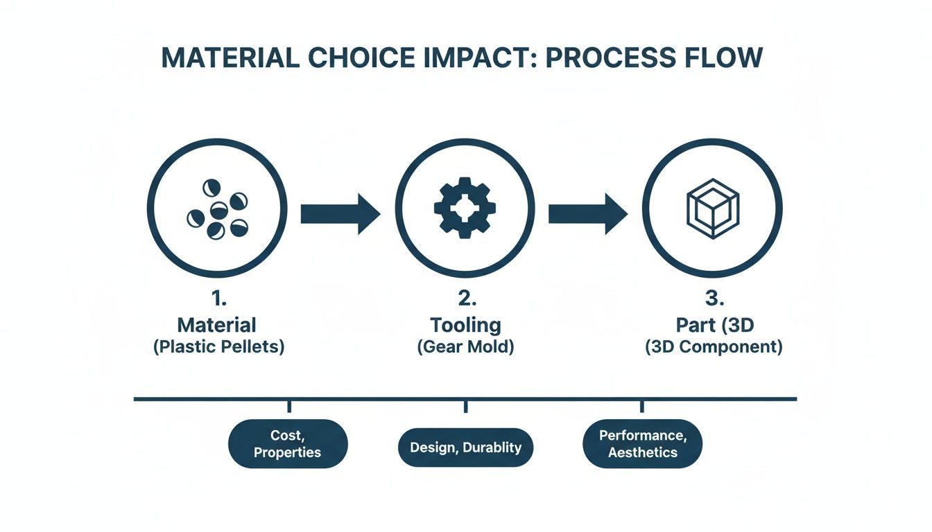
Polymer selection is a foundational decision that influences the entire project lifecycle. It extends beyond meeting mechanical and thermal specifications to directly dictating mold design, cost structure, and final part performance. Finalizing material choice before tool manufacturing commences is one of the most effective risk mitigation strategies available.
The most significant impact of material selection is on the mold itself. Every polymer has a unique shrink rate—the percentage it contracts upon cooling from a molten state. The toolmaker uses this value to machine the mold cavity, cutting it oversized to compensate for this shrinkage.
The Inescapable Link Between Material Shrink and Tooling
A common and costly error is assuming a mold can be repurposed for a different material.
For instance, a tool machined for ABS (typical shrink rate: 0.5-0.7%) cannot be used to produce dimensionally accurate parts from Polycarbonate (PC) (shrink rate: 0.6-0.8%). For any part with moderate to high tolerances, the resulting components will be out of specification. The issue is compounded with fiber-reinforced materials, which exhibit anisotropic shrinkage—shrinking differently in the direction of flow versus the cross-flow direction. The tool must be designed to account for this to prevent built-in warpage.
A material change after the tool is cut necessitates a “stop and re-evaluate” response. The associated costs include not only tool rework but also lost time, scrapped trial parts, and schedule delays that can jeopardize a product launch. Material selection must be finalized before tool steel is cut.
How Material Flow Affects Mold Design
A material’s flow characteristics, or viscosity, influence the design of gates and runners. High-viscosity materials like PC require larger gates and runners to ensure the cavity fills completely before the material solidifies. Conversely, low-viscosity materials like Nylon can fill thin, intricate features through smaller gates.
Adding fillers, such as glass fibers, dramatically increases viscosity and abrasiveness. This has two primary implications for the mold:
- Gate and Runner Design: The system must be engineered for higher injection pressures and to minimize shear on the fibers, which can degrade the material’s mechanical properties.
- Tool Steel Selection: Molds for abrasive materials require harder, more wear-resistant tool steels (e.g., P20, H13). This increases upfront tooling cost but is essential to prevent premature mold wear.
A full analysis of the injection molded plastics market highlights the growing complexity in material science. For specialized applications requiring high strength and thermal resistance, designers may need to delve into the properties and applications of phenolic resins to meet performance criteria.
Ultimately, mastering material selection requires understanding its direct and irreversible impact on tooling. Accounting for these factors from the outset provides a more predictable path to production.
A Pragmatic Workflow From CAD Model to Production Part
A disciplined workflow is a proven framework for mitigating risk, avoiding rework, and accelerating time-to-market. The process of converting a digital CAD model into a high-yield production part requires a clear plan that bridges design intent with manufacturing reality.
The workflow begins with a rigorous DFM analysis of the CAD model. Modern CAD platforms offer integrated mold-flow and DFM tools that can identify common issues like insufficient draft, inconsistent wall thickness, or areas prone to gas traps. These simulations are a mandatory first-pass sanity check.
Prototyping for Insight, Not Just Confirmation
After the initial DFM pass, prototyping is used to validate assumptions that cannot be tested digitally. The prototyping method must align with the learning objective.
- 3D Printing (FDM, SLA): Ideal for rapid, low-cost validation of form, fit, and ergonomics. These methods are not suitable for functional or mechanical testing, as the material properties and layer-based construction do not represent those of a molded part.
- Machined Prototypes (CNC): Essential for validating functional performance. A CNC prototype machined from a similar or identical polymer provides a true representation of the final part’s mechanical properties, making it the correct choice for load testing, impact resistance checks, and snap-fit validation.
Real-World Scenario: A Robotics Enclosure Failure
- Problem: A robotics startup designed a complex enclosure with delicate internal clips to secure a sensor package. They used 3D printing to validate form and fit, and the prototypes assembled perfectly.
- Diagnosis: The team skipped functional prototyping with a representative material. When the first production parts molded in ABS arrived from the $30,000 tool, the clips were brittle and fractured after minimal use.
- Solution: A mold modification was required to strengthen the clips, which involved costly and time-consuming tool rework.
- Outcome: The product launch was delayed by six weeks. A simple CNC-machined prototype, costing a few hundred dollars, would have identified this material-dependent failure mode early, preventing the significant financial and schedule impact.
The Critical Handoff to a Toolmaker
Once the design is validated and frozen, the information handoff to the toolmaker is a critical control point. A complete and unambiguous package is required to prevent misinterpretation.
The handoff documentation must include:
- Final 3D CAD Model: Provided in a neutral format like STEP or IGES.
- 2D Control Drawing: Specifies critical dimensions, tolerances, material specifications (including grade and manufacturer), and surface finish requirements.
- Parting Line and Gating Plan: A proposed or agreed-upon plan for the mold’s parting line and gate locations.
At Sheridan, our structured approach integrates these steps to achieve first-pass yields exceeding 95%. This disciplined process is essential for navigating the highly competitive U.S. contract molding market, which is projected to reach $19.4 billion by 2025.
Finalizing with Mold Trials and Inspection
The process concludes with the first article inspection (FAI) of T1 samples from the initial mold trial. These parts must be rigorously measured against the 2D control drawing. If discrepancies arise, teams must perform root cause analysis to determine if the issue stems from the part design, the tool, or the molding process. This iterative loop of testing, measurement, and adjustment is what stabilizes the process for high-volume production.
Industry-Specific Checklists for Medical and Aerospace Design
Standard DFM principles provide a baseline, but they are insufficient for highly regulated or performance-critical sectors like medical and aerospace. In these industries, best practices must be augmented with specialized requirements to manage compliance risk, ensure reliability, and meet extreme performance demands. Failure to address these industry-specific constraints early in the design phase introduces significant project risk.
Medical Device Design Checklist
In medical applications, DFM is inextricably linked with design for compliance. Every design decision must be justifiable under regulatory frameworks like ISO 13485.
- Material Traceability and Biocompatibility: Is the polymer supported by complete lot traceability from the manufacturer? Documentation must be available to prove the material meets biocompatibility standards (e.g., ISO 10993) for its intended level of patient contact.
- Sterilization Compatibility: The design must be compatible with the specified sterilization method (e.g., gamma irradiation, Ethylene Oxide, autoclave). Material selection is critical; for example, gamma radiation can cause embrittlement in polypropylene.
- Design for Cleanliness: Does the geometry contain features like sharp internal corners or deep crevices where bioburden could accumulate? Mating surfaces must be smooth and designed to prevent gaps that could harbor contaminants, a critical consideration for reusable instruments. Explore our portfolio of medical device engineering projects to see these principles in practice.
- Gate Vestige and Parting Line Location: Gate location must be specified on a non-critical surface to ensure any remnant does not interfere with function or compromise patient safety. Parting line flash must be controlled to prevent sharp edges.
Aerospace and Robotics Checklist
Aerospace and robotics applications demand maximum performance-to-weight ratios and unwavering reliability under harsh operating conditions, including mechanical stress, thermal cycling, and electromagnetic interference (EMI).
- Weight Reduction Strategies: Has mass been minimized without compromising structural integrity? This requires strategic use of ribs, coring out thick sections, and selecting high-strength, lightweight polymers.
- High-Performance Polymer Considerations: When using advanced materials like PEEK or Ultem, does the design account for their specific processing requirements, such as high melt temperatures and the need for tight process control to prevent material degradation and molded-in stress?
- Tight Tolerance Management: Are specified tight tolerances functionally required or a result of default settings? A formal tolerance stack-up analysis is mandatory for complex assemblies to ensure fit and function without incurring the high costs associated with unnecessary precision in tooling and quality control.
- Impact Resistance and Vibration Damping: For robotics applications, how will the component withstand impact and vibration? This may require adding gussets to strengthen bosses, using a fiber-reinforced material, or designing energy-absorbing features.
- EMI Shielding Integration: If the component houses sensitive electronics, has EMI shielding been considered? This can be achieved via a secondary coating process or by molding with a conductive-grade polymer. The part design must accommodate the selected method to ensure proper adhesion and electrical continuity.
By systematically addressing these industry-specific challenges during the design phase, teams can engineer a component that is not just manufacturable, but truly fit-for-purpose in its intended high-stakes environment.
Turning DFM Expertise Into a Competitive Advantage
Effective injection molding design is a strategic discipline that directly impacts cost, quality, and speed to market. The principles of uniform wall thickness, draft angles, and intelligent material selection are the foundational elements of predictable and efficient product development.
Integrating DFM expertise from the outset of the design cycle transforms manufacturing from a potential bottleneck into a competitive advantage. This approach mitigates the risk of costly, late-stage engineering changes and ensures a smoother path to production.
Complex projects, particularly in demanding sectors like medical devices or robotics, require deep cross-functional expertise. Design challenges often arise at the intersection of mechanical, electrical, and materials engineering, necessitating a holistic problem-solving approach.
The objective is to embed DFM as a core engineering competency, not a final checklist item. This mindset is what enables teams to achieve first-pass manufacturing success, minimize rework, and accelerate market entry.
At Sheridan Technologies, we provide on-demand access to specialists who apply these principles daily, ensuring your designs are optimized from day one.
To de-risk your next project and accelerate your path to a market-ready product, consider a complimentary design for manufacturability assessment with our engineering leads. It’s a low-friction way to validate your approach and walk away with actionable insights.
Burning Questions About Injection Molding Design
Here are direct answers to the critical DFM questions that engineering teams must address to mitigate risk and ensure production success.
What’s the Single Most Common—and Costly—DFM Mistake You See?
Without a doubt, it’s non-uniform wall thickness. It is the primary cause of a cascade of downstream production issues, including sink marks, warpage, and molded-in stress that leads to field failures.
Once the tool steel is cut, remediation is difficult and expensive. The best-case scenario involves welding and re-machining the mold cavity. The worst-case scenario is a complete tool rebuild, which results in significant schedule delays and budget overruns.
How Do I Decide Between Adding a Side-Action and Designing Out an Undercut?
This is a classic trade-off analysis, balancing part functionality against tooling cost and complexity. If an undercut is functionally non-negotiable—for a critical snap-fit latch, for instance—a side-action mechanism in the mold is required.
This decision increases tool cost by an estimated 15-30% and introduces mechanical complexity, which can reduce cycle time and increase long-term maintenance requirements. The initial design effort should always be to challenge the necessity of every undercut. A design modification can often achieve the same functional outcome without the associated cost and risk.
We always conduct a cost-benefit analysis for this decision. A $5,000 increase in tooling cost for a side-action may be justifiable for a high-volume part where the feature is essential. For a low-volume run, that same cost could render the project unviable, especially if an alternative two-part assembly could solve the problem.
When Exactly Should We Do a Formal DFM Analysis?
A formal DFM review should be a mandatory gate at two key stages of the development process, not a single event.
- Post-Concept CAD: The first review should occur immediately after a preliminary 3D CAD model is available. This is done before significant engineering hours are invested in detailed design or simulation based on a potentially flawed concept. This initial pass identifies major manufacturability issues early.
- Pre-Tooling Freeze: A second, more rigorous DFM review is non-negotiable immediately before the design is frozen for tooling quotation. This is the final opportunity to confirm that all details—including tolerances, material specifications, and surface finishes—are finalized and manufacturable. This review prevents costly, late-stage engineering change orders that disrupt production timelines.
At Sheridan Technologies, we integrate DFM analysis into every project to eliminate risk and accelerate your time to market. To ensure your design is optimized for first-shot success, schedule a complimentary DFM assessment with our engineering team.