Table of Contents
At its core, a SolidWorks configuration is a mechanism for creating multiple versions of a part or assembly within a single file. This concept is a cornerstone of efficient design, enabling teams to manage entire product families, custom options, and distinct manufacturing states—such as a raw casting versus the final machined part—without drowning in redundant, disconnected models.
Using configurations, an engineering team can parametrically control dimensions, features, materials, custom properties, and assembly mates. It is the fundamental tool for generating an entire product line from one master model, establishing a single source of truth that mitigates downstream manufacturing and supply chain risks.
Why SolidWorks Configurations Are a Strategic Tool
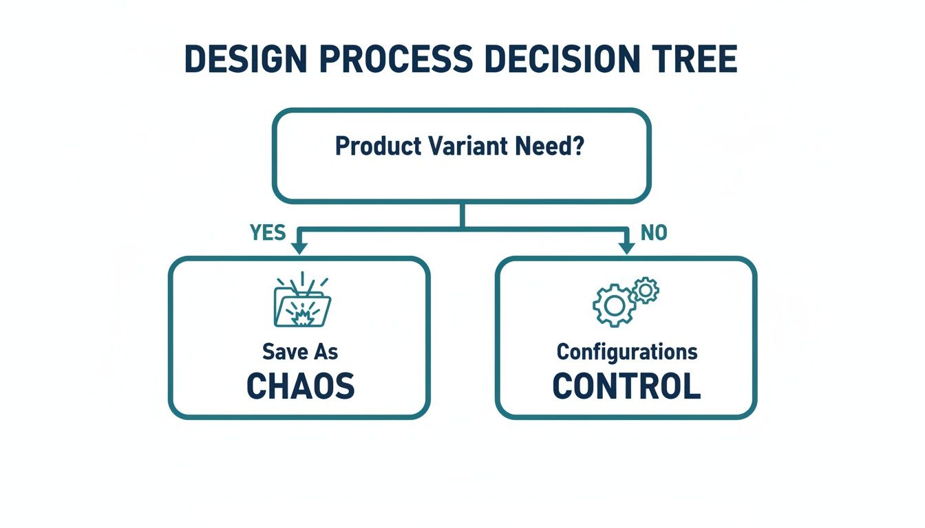
Problem: A common failure mode in engineering departments is the proliferation of slightly different product files driven by one-off customer requests. A customer needs a mounting bracket with three holes; another wants the same bracket, but 50mm longer and fabricated from stainless steel. The typical reaction is “Save As,” resulting in a directory filled with bracket_v1.sldprt, bracket_v2_long.sldprt, and bracket_v3_ss.sldprt.
Diagnosis: This reactive approach introduces significant operational risk. It creates a data management liability where tracking the correct revision is guesswork. Inevitably, the wrong file is sent to manufacturing, resulting in scrap, rework, and schedule delays. This “Save As” engineering methodology is brittle, error-prone, and unscalable.
Solution: The strategic solution is to implement a disciplined workflow built around configurations in SolidWorks. Instead of dozens of disconnected files, the team creates a single, intelligent master file that houses every possible variation. This file becomes the validated single source of truth for the entire product family. This work is primarily managed in the ConfigurationManager tab, which provides a tree-like view of all variations within the file.
Outcome: The business impact is immediate and measurable. By centralizing design intelligence, you directly reduce rework, accelerate the quoting process for custom variants, and simplify design validation. For teams in regulated environments like medical devices (ISO 13485) or aerospace (DO-178C), this structured approach is essential for maintaining rigorous design control and traceability, directly reducing compliance risk.
Establishing a Single Source of Truth
Since their introduction, configurations have evolved from a niche parametric feature into a core productivity engine. It’s no surprise that a significant portion of the SOLIDWORKS user base—nearly 85%—is in small and mid-market firms where design reuse and automation deliver critical leverage. Many of these users are in the industrial machinery sector, which depends on configurable assemblies and product options.
This widespread adoption underscores a key point for any engineering manager: mastering configurations is no longer an optional skill but a competitive necessity for improving speed to market and controlling costs.
By consolidating product variations into a master model, teams can drastically cut down on data management overhead and reduce the risk of sourcing or manufacturing the wrong component version. This isn’t just a CAD technique; it’s a risk reduction strategy.
Ultimately, this approach transforms the design process from a collection of disconnected tasks into a cohesive, manageable system. By making design variations auditable and reducing manual errors, SolidWorks configurations are a fundamental part of strategies to enhance manufacturing productivity. The result is a more agile engineering department that can respond to market demands with greater speed and accuracy.
Choosing Your Configuration Method: Manual vs. Design Tables
Once a configuration-driven workflow is adopted, the next critical decision is the implementation method. SOLIDWORKS provides two primary paths: adding configurations manually or automating the process with an Excel-based Design Table.
Selecting the appropriate method is the difference between a clean, scalable design asset and a new form of digital chaos.
This decision is a fundamental fork in the road for any project requiring part variations. The initial choice to use configurations in SOLIDWORKS establishes control; the next step is selecting the right tool for the required complexity and scale.
When to Stick with Manual Configurations
The manual route—using the “Add Configuration” command in the ConfigurationManager—is direct and efficient for simple, low-count variations. It is the optimal choice for managing a few distinct states that do not share a complex parametric relationship.
Use Case: An enclosure for a medical device must accommodate two different printed circuit board (PCB) layouts. One version has a cutout for an LCD screen and associated mounting bosses, while the other is a blank faceplate.
- Configuration A:
With_Display - Configuration B:
No_Display
In this scenario, creating two configurations manually is the most efficient method. The second configuration is created by simply suppressing the features for the cutout and bosses. It’s quick, intuitive, and avoids the overhead of external tools. The primary failure mode of the manual method emerges with scale. Managing ten, twenty, or fifty configurations by hand is not just tedious; it’s a direct path to human error.
Scaling Up with Design Tables
When complexity increases, Design Tables become the only practical, scalable solution. A Design Table is an embedded Microsoft Excel spreadsheet within the SOLIDWORKS file that can drive nearly any parameter in the model. This is the standard method for creating large families of parts driven by specific rules.
Use Case: The same medical enclosure product line expands. The design must now support multiple versions based on several independent parameters:
- Length: 100mm, 150mm, 200mm
- Material: ABS, PC-ABS, Aluminum
- Connector Type: USB-C, DB9, Circular
- Finish: Textured, Smooth
Manually creating every permutation (3 lengths x 3 materials x 3 connectors x 2 finishes = 54 configurations) would be untenable and prone to error. This is the problem Design Tables are designed to solve.
A Design Table provides a centralized, tabular interface to control all driving parameters. It transforms a complex management problem into a data-entry task, dramatically reducing the risk of manual errors and ensuring consistency across the entire product family.
The table offers a comprehensive overview of the product family, simplifying the process of adding new variations or modifying existing ones by adding or editing a row.
Comparing the Methods
Choosing between these two approaches involves clear trade-offs. The manual method is faster for simple cases, while Design Tables offer robust control required for scale.
| Comparison of Configuration Creation Methods |
| :— | :— | :— |
| Attribute | Manual Configurations | Design Tables (Excel-based) |
| Best For | A small number of distinct variations (e.g., < 5) with on/off features. | Large part families, parametrically-driven designs, and complex variations. |
| Setup Time | Very fast; right-click and add. | Higher upfront effort; requires setting up the table and linking parameters. |
| Scalability | Poor. Becomes unmanageable and error-prone as variations increase. | Excellent. Can manage hundreds or thousands of configurations efficiently. |
| Error Potential | High for large numbers; easy to forget to suppress/unsuppress a feature. | Low; parameters are centrally controlled, ensuring consistency and auditability. |
| Ease of Editing | Simple for one-off changes, but tedious and risky for bulk updates. | Efficient for bulk edits; update the spreadsheet. Can be edited externally. |
| Visibility | Requires clicking through each configuration to verify its state. | Provides a clear, at-a-glance overview of all variations in a single table. |
Practical Tradeoffs and Final Recommendations
Regardless of the method, a disciplined naming convention is non-negotiable. For Design Tables, it is critical. Use descriptive names like ENC-150-ABS-USBC-TEX to encode key parameters directly into the configuration name. This improves clarity in assemblies, drawings, and PDM systems.
For parts intended for manufacturing processes like injection molding, a Design Table is invaluable. It can control parameters like draft angles or material-specific shrinkage rates for different polymers. Properly structuring this data is a key component of successful part design, a topic covered in our guide on designing for injection molding. This level of parametric control enables manufacturability to be built directly into the master model from the outset.
Recommendation: For a handful of binary states, use the manual method. For anything involving parametric families or more than five variants, invest the upfront time to build a well-structured Design Table. This initial effort pays dividends by preventing errors, simplifying future updates, and reducing long-term maintenance costs.
Advanced Control Over Features, Mates, and Assemblies
Parametric dimension changes are foundational, but the strategic value of configurations in SolidWorks is realized through granular, state-dependent control over every model detail. This enables the creation of intelligent systems that manage complex assembly logic, rather than just simple part families.
Problem: A common failure point is a configuration that rebuilds with unexpected geometry or a cascade of broken mates. The root cause is almost always features and mates left in their default state, allowing them to solve unpredictably as other components change.
Diagnosis: Without explicit control, a master model can become a source of cascading errors. The lack of deterministic control over suppression states and properties for every critical feature and mate leads to unpredictable and unreliable models.
Solution: The only way to build a robust model is to proactively manage the suppression state and properties of every critical feature and mate for each configuration. This ensures that each variant is not just a collection of different dimensions, but a truly independent and stable design state.

Real-World Scenario: Robotic Gripper Variants
Consider a configurable robotic gripper assembly that must support multiple end-effectors, sensor packages, and mounting interfaces. Managing this with a “Save As” workflow would be a high-risk exercise in file management and revision control. Instead, configurations are used to manage this complexity within a single master assembly.
The required product matrix includes:
- Gripper Type: Parallel 2-jaw vs. Concentric 3-jaw.
- Sensor Package: Proximity sensor vs. Vision system.
- Mounting Interface: Standard ISO 9409-1-50-4-M6 vs. a custom dovetail mount.
Each combination is a deliverable product. Managing this requires precise control over not only which parts are present, but also how they are mated and interact.
Suppressing Features and Components
The most direct control mechanism is the suppression state. Suppressing a feature or component instructs SolidWorks to ignore it for a specific configuration. It is not deleted, merely deactivated for the calculation. This is more efficient and reliable than using equations to “zero out” a feature’s dimensions.
This is managed by right-clicking a feature or component in the FeatureManager Design Tree and selecting Configure Feature or Configure Component. This opens a table to control the suppression state across all configurations.
For the gripper assembly, the control table would look like this:
- Mounting Holes: Features for the ISO bolt pattern are unsuppressed in the
ISO_Mountconfiguration but suppressed in theDovetail_Mountconfiguration. - Sensor Brackets: The vision system’s mounting bracket is suppressed in any
Prox_Sensorconfiguration, and vice versa. This prevents physical interference and ensures an accurate Bill of Materials. - Gripper Jaws: The entire subassembly for the 3-jaw mechanism is suppressed when any
2-Jawconfiguration is active.
This provides an explicit, auditable table defining the active state for each variant, eliminating guesswork and ensuring correct builds.
By explicitly controlling the suppression state of features and components for each configuration, you create a deterministic model. This prevents ambiguous rebuilds and is the foundation for reliable, automated drawings and BOMs, directly reducing the risk of costly manufacturing errors.
Configuring Mates for Kinematic States
This control can be extended to the mates themselves. This is useful for representing an assembly in different positions or operational states without creating separate files. Mates can be suppressed, and their driving values (e.g., distance, angle) can be tied to the active configuration.
For the robotic gripper, this allows for documenting various jaw positions:
Jaw_Fully_OpenJaw_Fully_ClosedJaw_Grip_50mm
This is achieved using the Configure Feature command on the distance mate controlling the jaw opening, entering a different value for each configuration. Mate suppression is also a powerful technique. For example, a “shipping” configuration might enable a Fixed mate to lock the mechanism. This mate would be suppressed in all “operational” configurations to allow free movement.
The Business Impact of Granular Control
This level of detailed control directly impacts operational efficiency and risk. When each configuration is reliably defined, downstream processes can be automated with high confidence.
| Benefit | Business Impact |
|---|---|
| BOM Accuracy | Guarantees only the correct components appear on the parts list for each variant, preventing incorrect purchasing and assembly. |
| Drawing Automation | Drawings with views tied to specific configurations update reliably, slashing manual cleanup time and reducing drafting errors. |
| Reduced Rework | Prevents the shop floor from receiving ambiguous or incorrect models, cutting down on scrap, rework costs, and schedule delays. |
| Faster Quoting | Allows sales and application engineers to quickly cycle through pre-defined, validated configurations to meet customer requirements. |
Outcome: The result is a single, intelligent master model that drives the entire product development process. It’s an upfront investment in creating a predictable and scalable system, shifting the team from a reactive, problem-fixing posture to a proactive, configuration-driven workflow.
Tying It All Together: Configurations, BOMs, and PDM Systems
Problem: A perfectly configured model is operationally useless if it leads to incorrect part procurement or manufacturing. The value of configurations in SolidWorks is only realized when they integrate seamlessly with downstream systems—specifically, the Bill of Materials (BOM) and Product Data Management (PDM) systems.
Diagnosis: The most common point of failure is the generation of accurate, configuration-specific BOMs. An engineer may model dozens of variants, but if the drawing’s BOM does not update to reflect these changes, the effort is wasted. This disconnect is how procurement orders incorrect quantities and the shop floor builds the wrong assembly version. The root cause is almost always poorly managed part numbers and custom properties. Simply changing a dimension is insufficient; each manufacturable variant requires a unique identity.
Solution: The fix is to embed intelligence directly into each configuration using configuration-specific custom properties. This requires assigning a unique part number, description, and material to each configuration that represents a deliverable item. This is most efficiently managed in a Design Table by adding columns for properties like $PARTNUMBER, Description, and Material, automatically populating this critical metadata for every variant.
When a configured part is placed in a drawing, the BOM table is set to pull this configuration-specific data. Now, when a user activates the Long_Version configuration, the BOM correctly displays its unique part number, not the default.
A BOM that doesn’t accurately reflect the chosen configuration is a direct path to manufacturing errors and supply chain chaos. Using configuration-specific properties to drive your BOM data isn’t just a good idea—it’s a non-negotiable best practice.
Real-World Scenario: Manufacturing States
A common workflow involves a welded frame assembly that requires machining after fabrication. This process requires documentation for two distinct manufacturing states.
- As-Welded: This configuration shows the raw weldment and is used for the fabrication drawing sent to the welding shop.
- As-Machined: This is a derived configuration showing the same weldment but with post-machining features (e.g., faced-off surfaces, drilled holes) unsuppressed.
The final assembly BOM must call out the part number for the finished, machined frame. By assigning unique part numbers to both the As-Welded and As-Machined configurations within the part file, the assembly BOM automatically pulls the correct identifier based on which version is placed in the assembly. This ensures clarity and accuracy.
Why PDM Integration is a Must-Have
Managing files with numerous configurations without a PDM system is a high-risk activity. The probability of broken references, overwritten data, or team members working on outdated versions increases dramatically. A system like SolidWorks PDM imposes order on this potential chaos.
A PDM system treats each configuration as a unique, revision-controlled item. It understands parent-child relationships and allows you to:
- Assign Unique Item Records: Each configuration receives its own record in the PDM vault, with an independent lifecycle and revision history.
- Control Revisions Independently: A revision to the
As-Machinedconfiguration (e.g., to Rev B) does not affect theAs-Weldedconfiguration, which can remain at Rev A, ensuring complete traceability. - Prevent Data Catastrophes: PDM’s check-in/check-out protocol prevents one engineer from overwriting another’s changes to a different configuration within the same file.
Without PDM, an engineer updating one configuration could unknowingly break another—a rebuild error that might not be detected until a faulty part reaches manufacturing. PDM provides the necessary guardrails to prevent these costly, invisible failures. This discipline is tied to the broader product configurator software market, a sector projected to reach USD 3.5 billion by 2031, reflecting an industry-wide shift toward managing complex, variant-rich data. The key drivers are detailed in reports covering the growth of product configurator software.
Optimizing Performance and Avoiding Common Pitfalls
Problem: While powerful, configurations in SolidWorks can severely degrade model performance if mismanaged. The classic failure mode is cramming hundreds of complex variations into a single master file, resulting in slow load times, frequent rebuilds, and model instability. The business impact is lost engineering hours and project delays.
Diagnosis: The performance degradation typically stems from two sources: excessive geometric detail stored in one file and a tangled web of in-context relationships that force the system to check every change against dozens of other configurations. SOLIDWORKS attempts to load significant configuration data into memory, even for inactive variants, leading to bloat.
Solution: The fix requires a strategic approach to isolating complexity. Instead of adding configurations reactively, complexity must be compartmentalized from the outset.

Isolate and Simplify Complex Sub-Assemblies
An effective strategy is to treat highly configurable sub-assemblies as self-contained “black boxes.” Inserting a component with 150 configurations directly into a top-level assembly is a direct path to performance failure.
Instead, create a dedicated lightweight configuration for such components. This simplified version should contain only the minimal geometry required for mating and clearance checks, with all complex internal details suppressed. This dramatically reduces the memory load on the main assembly, as the full, detailed version is only loaded when that sub-assembly is opened directly.
Use Case: A configurable electrical enclosure contains detailed PCBs, connectors, and wiring.
- Default Configuration: Shows every component in full detail.
- Simplified Configuration: All internal components are suppressed, leaving only the exterior shell with critical mounting points and interface geometry.
Within the main machine assembly, use the Simplified configuration. This prevents SOLIDWORKS from wasting resources on internal parts it doesn’t need to render, resulting in faster load times and smoother model manipulation. This is especially crucial when dealing with detailed parts; as our guide on PCB design for manufacturing highlights, the intricacy of board layouts can significantly degrade overall assembly performance.
Proactive Troubleshooting for Common Failure Modes
Even with a sound structure, issues will arise. The most common are rebuild errors that only manifest in a specific, rarely-used configuration, typically caused by a change in one variant having an unintended consequence in another.
To mitigate this, establish a process for regularly performing a full rebuild of all configurations. Use the Rebuild on Save Mark command (Ctrl+Q) to force a deep rebuild. For files with many configurations, right-click the file name at the top of the ConfigurationManager and select Rebuild All Configurations.
File bloat is another performance killer. Over time, configuration data can leave cached geometry that inflates file size. The Purge command, found in the Design Table properties, strips out cached configuration data no longer active in the Design Table, often resulting in a significant reduction in file size and improved load times.
The most stable configured models are those where complexity is intentionally isolated. Treating configurable sub-assemblies as simplified components within a larger assembly is the single most effective technique for maintaining performance and stability at scale.
Improving Usability with the Configuration Publisher
Presenting dozens of options as a long, flat list creates a poor user experience. The Configuration Publisher is an underutilized tool that allows you to build a clean, custom PropertyManager interface for selecting options.
Instead of a single dropdown with 50 cryptic names, you can create a user-friendly panel with logical controls:
- Dropdown list for Length (100mm, 150mm, 200mm)
- Checkbox for With Mounting Bracket
- Radio buttons for Material (Steel, Aluminum)
This tool acts as a smart filter for existing configurations. Its value lies in error reduction, making the master model more approachable and foolproof for other users, ensuring the correct variant is specified.
Implementing a Configuration-Driven Design Strategy
configurations in SOLIDWORKS are a strategic tool for managing complexity, but success depends on a disciplined approach to controlling features, mates, and data within a PDM framework. Without this structure, a master model can become a source of risk rather than a competitive asset.
The most effective way to begin is by auditing a current product family currently managed through a “Save As” workflow. These are prime candidates for consolidation into a single, intelligent master file. This initial project serves as a low-risk pilot to demonstrate the value of a configuration-driven approach.
Proving the Return on Investment
This strategic shift directly impacts speed, risk, and cost. A multi-industry survey found that 54% of companies reported getting products to market faster after adopting such workflows, with an average improvement of 16.6%. These gains are driven by features like configurations and Design Tables that eliminate redundant design work. The underlying data is available in this SOLIDWORKS ROI report.
This methodology also aligns with key principles of efficient production. By embedding manufacturability rules directly into different configurations, your team can proactively mitigate downstream issues. These concepts are explored in our guide on Design for Manufacture and Assembly, where a well-managed master model is the critical foundation.
Your Path Forward
For engineering leaders, the next step is to de-risk complex projects and enhance team efficiency. A configuration-driven workflow is not an overnight switch but a gradual implementation of best practices, starting with identifying a suitable candidate product and establishing clear data management standards.
The ultimate goal is to transform your CAD library from a simple archive of static files into a dynamic system that actively accelerates product development and reduces operational friction. This establishes a scalable foundation for future innovation.
This disciplined approach ensures your engineering data becomes a reliable, predictable asset that supports the entire product lifecycle. The outcome is not just better organization, but a more agile and resilient product development process.
For leaders looking to de-risk a complex project or improve team efficiency, the logical next step is an expert consultation. Sheridan Technologies can assess how configuration-driven workflows could be implemented or optimized within your specific product development context. Contact us to schedule a brief consultation at https://sheridantech.io.