
Table of Contents
A working prototype is a critical milestone, but it’s not the finish line. Many technical teams celebrate this achievement only to find the transition to a reliable, manufacturable, and commercially viable product is a fundamentally different challenge. It requires a shift in mindset—from proving a concept can work to engineering a system that will work repeatably, at scale, and under real-world stress.
This guide provides a practical roadmap for navigating that transition, focusing on the critical engineering disciplines and validation stages required to de-risk the journey from prototype to production.
The Gap Between a Prototype and a Product
The core conflict is that the priorities for building a prototype are often antithetical to those of a production-ready product. Prototypes are optimized for speed and flexibility, using readily available components to validate a core hypothesis. A product, however, demands reliability, cost-efficiency, scalability, and consistency. This disconnect is a primary source of project failure.
Before committing to manufacturing, it is essential to first build an MVP to validate your idea and confirm market demand. Manufacturing a product nobody is willing to buy is a terminal error. The following table illustrates the strategic pivot required after market validation is achieved.
Prototype Focus vs. Product Focus: A Strategic Comparison
| Attribute | Prototype (Proof of Concept) | Product (Ready for Market) |
|---|---|---|
| Primary Goal | Prove core functionality works. | Deliver a reliable, scalable, and profitable solution. |
| Component Selection | Speed & availability. What’s on hand? What’s easy? | Cost, lead time, lifecycle, multiple sources, reliability. |
| Assembly | Manual, one-off assembly. Often by an engineer. | Designed for automated assembly (DFM). Repeatable. |
| Firmware/Software | Basic functionality. Minimal error handling. | Hardened, secure, OTA updates, robust error handling. |
| Enclosure/Mechanics | 3D printed, off-the-shelf, or non-existent. | Injection molded, tooled for volume, tested for durability. |
| Testing | Ad-hoc functional checks on a lab bench. | Rigorous, automated validation and verification (V&V). |
| Cost Focus | Minimal upfront cost to prove the concept. | Lowest possible Cost of Goods Sold (COGS) at scale. |
| User Experience | An afterthought. Function over form. | Central to the design. Polished and intuitive. |
This highlights the shift from exploratory development to disciplined engineering. The transition demands a systematic approach that accounts for the realities of supply chains, manufacturing processes, and deployment environments.
Why Early Decisions Have an Outsized Impact
Engineering decisions made during the initial design phase dictate the majority of a product’s lifecycle cost. Industry analysis indicates that approximately 80% of a product’s total lifetime cost is locked in during design, long before any volume production orders are placed.
Choices regarding component selection, PCB architecture, enclosure materials, and test strategy directly determine the Cost of Goods Sold (COGS), long-term reliability, and serviceability. For example, a component chosen for a prototype due to immediate availability might have a volatile supply chain or a short production lifecycle, forcing a costly redesign later. Similarly, firmware developed without robust error handling may function on a lab bench but will inevitably fail in unpredictable field conditions.
Studies of new product development estimate that up to 90% of new product initiatives fail, often because teams never translate a promising prototype into something manufacturable and reliable at scale. This highlights a critical gap between innovation and execution.
Common Failure Modes in the Transition
The path from prototype to product is fraught with predictable and avoidable failure modes. Recognizing these is the first step toward effective risk mitigation.
- Designing for One-Off Assembly: Prototypes are typically hand-built by their designers. Production units must be designed for automated or semi-automated assembly, requiring consideration of component placement, clearances, pick-and-place machine limitations, and tooling from the outset.
- Ignoring Component Lifecycle: A frequent error is using components that are near end-of-life (EOL) or available only from a single source. A production-ready design prioritizes components with long, stable lifecycles and qualified second sources to mitigate supply chain risk.
- Underdeveloped Firmware: Prototype firmware often lacks production-critical features like a secure bootloader, over-the-air (OTA) update capabilities, or comprehensive error handling. A field failure requiring a physical recall can be a catastrophic business event.
- Neglecting DFM and DFT: Design for Manufacturability (DFM) and Design for Test (DFT) are essential disciplines for creating a product that is cost-effective to build and validate. Bypassing this step leads to low manufacturing yields, increased costs, and inconsistent quality.
Hardening Your Hardware and Firmware for Production
A lab prototype is a fragile system, shielded from the environmental and operational stresses of the real world—temperature extremes, unstable power, and unpredictable user interactions. Moving that prototype into production without a disciplined hardening process is a direct path to field failures, expensive recalls, and reputational damage.
This phase is not about adding features; it is about engineering for resilience and reliability.
Problem: Prototype hardware, often built on development kits with accessible headers and forgiving layouts, is fundamentally unsuited for mass production. The corresponding firmware, typically a simple polling loop with minimal error checking, will fail under the dynamic pressures of deployment.
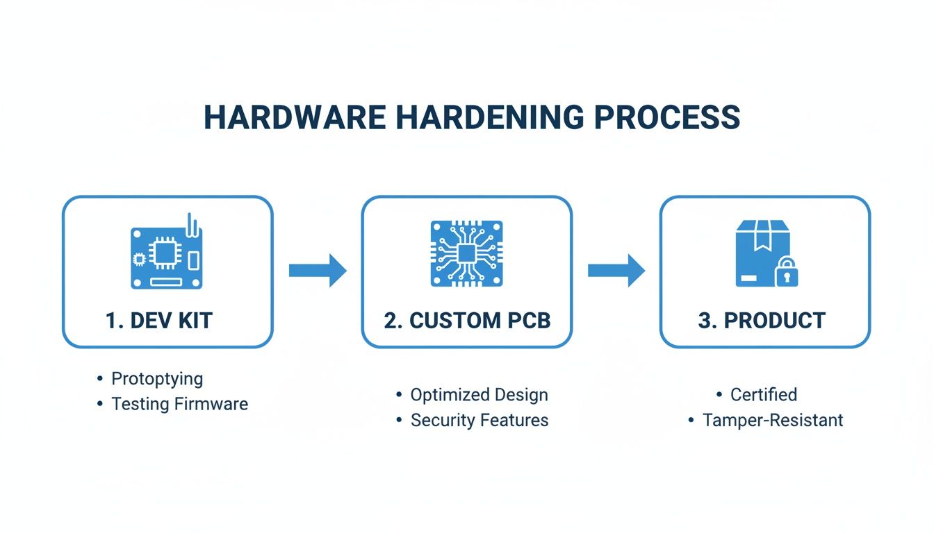
From Development Kit to Custom PCB
The transition from a development board to a custom Printed Circuit Board (PCB) is a pivotal step. The focus shifts from proving a concept to engineering a manufacturable asset, governed by two critical disciplines: Design for Manufacturability (DFM) and Design for Test (DFT).
DFM is concerned with designing a board that can be built efficiently and cost-effectively at scale.
- Strategic Component Selection: Sourcing must prioritize components with long production lifecycles, stable supply chains, and multiple vendors. Package sizes should be compatible with automated pick-and-place equipment, not optimized for manual soldering.
- Thermal Management: Production units operate in diverse environments. The PCB layout must act as an effective thermal conductor, dissipating heat from components like processors and power regulators to prevent thermal throttling or premature failure.
- Signal and Power Integrity: A dense production board requires careful layout to manage high-speed signal integrity (preventing crosstalk) and control electromagnetic interference (EMI). Failure to do so can cause unreliable operation and guarantee failure during regulatory certification (e.g., FCC, CE).
DFT involves designing a board that can be tested efficiently during production. Integrating accessible test points for critical signals enables automated in-circuit testing (ICT) or functional circuit testing (FCT). A robust test strategy is a primary pillar of quality control. For more detail, our guide on how to test a circuit board provides practical implementation guidance.
Fortifying Your Firmware for the Field
Production-grade firmware must be architected for resilience, efficiency, and long-term maintainability.
The most critical architectural shift is from a linear, polling-based execution model to a robust, event-driven system. The product must handle faults gracefully and maintain operation under stress. This is non-negotiable for any deployed system.
This hardening process includes several key upgrades:
- Adopt an Interrupt-Driven Architecture: A
while(1)polling loop is power-inefficient and unresponsive. A production system should be interrupt-driven, allowing the processor to enter low-power sleep states until an event (e.g., sensor input, timer) requires action. - Implement a Watchdog Timer: A hardware watchdog timer is a critical safety mechanism that automatically resets the processor if the firmware becomes unresponsive. Correct implementation and servicing of a watchdog is the first line of defense against unforeseen software lockups.
- Integrate Secure Over-the-Air (OTA) Updates: No firmware is perfect. A secure bootloader and a reliable OTA update mechanism are essential for deploying bug fixes and feature updates without requiring a physical recall, directly reducing long-term operational costs and risk.
- Systematic Power Optimization: For battery-powered devices, this involves aggressive management of sleep modes, peripheral power gating, and dynamic clock frequency scaling to maximize operational life.
A Real-World Failure Scenario
Problem: An industrial IoT company developed a sensor for monitoring fluid levels in remote tanks. The prototype performed flawlessly in the lab. However, upon deploying several hundred units, intermittent failures began. Units would drop offline for hours before reappearing, causing significant data gaps and jeopardizing a major contract. The cost of dispatching technicians to remote sites was becoming prohibitive.
Diagnosis: Root cause analysis revealed the firmware was built on a simple polling loop. Under certain network latency conditions, a blocking network call would prevent the main loop from servicing the watchdog timer. The watchdog would correctly interpret this as a system crash and trigger a reboot. The absence of persistent error logging made remote diagnosis extremely difficult.
Solution: The firmware was re-architected to an event-driven model using a real-time operating system (RTOS). This eliminated blocking calls. The team implemented robust error handling that logged fault codes to non-volatile memory before a reboot and ensured the watchdog was serviced by a high-priority, independent task. A secure OTA mechanism was also added to deploy the fix remotely.
Outcome: The redesigned firmware eliminated the field failures. The new OTA capability allowed the company to update all deployed units without a single site visit, saving an estimated $250,000 in recall and service costs and salvaging the customer relationship. This demonstrates that hardening is not an optional polish but a core requirement for transforming a prototype into a viable product.
Navigating the Manufacturing Gauntlet: From EVT to PVT
Once the design is hardened, it must face the realities of mass production. A structured validation process is required to systematically de-risk both the product and the manufacturing line. This process is divided into three distinct stages: Engineering Validation Test (EVT), Design Validation Test (DVT), and Production Validation Test (PVT). Each phase has a clear mission and exit criteria. Skipping a stage is a common but costly error.
Engineering Validation Test (EVT): The First Litmus Test
Goal: Verify that the core design is functional.
EVT is the first build of the custom hardware, typically a small batch of 10-50 units, which may be assembled in-house. The focus is on fundamental design validation.
- Board Bring-Up: Does it power on? Can firmware be flashed? Are core subsystems (processor, memory, power rails) operating as expected?
- Mechanical Fit: Do all electrical and mechanical components fit together as designed in CAD?
- Identify Major Flaws: EVT is designed to uncover critical errors such as incorrect component footprints, major PCB layout flaws, or fundamental architectural issues that necessitate a board respin.
The primary output of EVT is not a saleable product but a detailed bug list and a set of revisions for the next hardware iteration. Successful completion of EVT means you have a design that meets its core functional requirements.
Design Validation Test (DVT): Forging a Resilient Product
Goal: Validate that the design meets all performance, environmental, and regulatory specifications.
DVT involves a larger build of 50-200 units using production-intent tooling and processes, typically performed at the selected contract manufacturer (CM). This stage is about subjecting the design to rigorous stress testing.
This methodical progression is what creates a design that can survive the battery of tests in this phase.
Key DVT activities include:
- Environmental Stress Testing: Units are subjected to temperature cycling, humidity, vibration, and shock testing to identify design weaknesses.
- Regulatory Pre-Compliance: Testing for standards like FCC/CE (electromagnetic compatibility) and UL/IEC (safety) is performed to identify and fix issues before formal certification.
- Full Specification Verification: The product is tested against every line item in the engineering requirements document across all specified operating conditions.
A successful DVT provides high confidence that the hardware design is final. Upon exiting DVT, a “design freeze” is typically enacted. Subsequent hardware changes require a formal, and often costly, re-validation process.
Production Validation Test (PVT): Putting the Factory to the Test
Goal: Validate the manufacturing line and process.
With PVT, the focus shifts from testing the product’s design to testing the manufacturer’s ability to build it at scale, on budget, and to the required quality standard. This is the first official production run, and the resulting units are expected to be saleable.
Activities include dialing in assembly line yield rates, finalizing quality control checkpoints, and qualifying test fixtures. It also serves as a final verification of the supply chain’s capacity to handle production volume. Our guide on Design for Manufacturability and Assembly provides deeper insight into preparing a design for this stage.
Adherence to this disciplined process is crucial. According to the WIPO Global Innovation Tracker, while overall R&D growth has slowed, R&D intensity at top firms has climbed to 5.5%, its highest since 2018. The pressure to execute correctly the first time is immense, driving the R&D outsourcing market toward a projected $14 billion by 2029. You can find more on these global R&D trends from WIPO.
Successfully exiting PVT signals readiness for mass production. The EVT-DVT-PVT process systematically removes risk, ensuring the product launched can be built reliably and profitably.
Integrating Compliance into Your Design Process
For products in regulated industries such as medical devices (e.g., IEC 62304), aerospace (e.g., DO-178C), or industrial automation (e.g., UL), compliance is not a final step but a core design constraint. Treating certification as a post-design checkbox is a common cause of catastrophic delays and budget overruns.
Problem: A frequent mistake is deferring compliance considerations until the DVT stage. Testing a design that was not optimized for regulatory requirements often reveals deep architectural flaws, forcing extensive and costly redesigns late in the development cycle.
Solution: The effective approach is to embed compliance requirements into the development lifecycle from the outset, treating it as a parallel engineering track that informs all design decisions.
Building Your Compliance Foundation Early
This begins with a robust Quality Management System (QMS). A QMS provides the operational framework for enforcing traceability, risk management, and documented evidence for every engineering decision.
For medical devices, this is formalized under ISO 13485. A key component is the Design History File (DHF), which serves as the auditable record of the entire design process. Every requirement, specification, design output, verification test, and validation result must be meticulously documented. This enforces internal discipline and provides the objective evidence required by regulatory bodies like the FDA.
A core activity within this framework is risk analysis, guided by standards like ISO 14971 for medical devices. This systematic process involves identifying potential hazards, estimating their severity and probability, and designing specific mitigations into the hardware and firmware.
A Real-World Use Case: Industrial Control Certification
Problem: A team developed a functional prototype for an industrial controller intended for factory automation. The design, however, completely ignored UL electrical safety standards. The enclosure used a non-flame-retardant plastic, internal wiring lacked proper strain relief, and high-voltage traces on the PCB had insufficient clearance from low-voltage circuits.
Diagnosis: A pre-compliance audit revealed that the design would fail multiple fundamental UL tests. The necessary changes were not minor tweaks but required scrapping the enclosure tooling and a complete PCB respin, representing a major schedule and budget impact.
Solution: The next design iteration integrated compliance from the start.
- Component Selection: A UL94 V-0 rated polymer was specified for the enclosure, and only UL-recognized power supplies and connectors were used.
- Mechanical Design: The enclosure was redesigned for proper thermal management and included secure mounting points for all components to ensure electrical safety.
- PCB Layout: The board was laid out with clear physical segregation between high-voltage and low-voltage sections, adhering strictly to the creepage and clearance rules defined in IEC 60950-1.
This proactive approach transformed compliance from a pass/fail gate into a set of known design constraints. The team shifted from testing against the standard to designing to the standard.
Outcome: The redesigned product passed formal UL testing on the first attempt. This strategy prevented an estimated six-month delay and over $100,000 in scrapped tooling and redesign costs. Integrating compliance early de-risks the entire project and accelerates market entry. It is also a critical component of a layered defense, as detailed in our guide to security in embedded systems, where regulatory and security requirements often overlap.
Using Digital Engineering to Accelerate Timelines
Traditional product development relied on a linear “build-and-break” cycle: construct a physical prototype, identify its flaws through testing, and repeat. This iterative process is a notorious consumer of time, capital, and materials, forcing teams to make critical design decisions with incomplete information.
Modern digital engineering tools invert this model, enabling teams to front-load discovery and solve complex problems in a virtual environment before committing to physical hardware.

Simulating Performance Before Building Hardware
Simulation software allows engineering teams to answer critical questions that once required a physical prototype. Instead of building a PCB to discover it overheats, its thermal performance can be modeled under various load conditions. This is a fundamental risk mitigation strategy employed before committing to expensive tooling.
Simulation provides a decisive advantage in several key areas:
- Thermal Analysis: Identify hotspots on a PCB or within an enclosure and virtually test mitigation strategies like adding heatsinks or optimizing airflow. This prevents field failures due to thermal throttling or component damage.
- Structural Integrity (FEA): Use Finite Element Analysis to simulate the product’s response to real-world mechanical stress, such as vibration, shock, and torsion, ensuring durability without over-engineering and adding unnecessary cost or weight.
- Electromagnetic Compatibility (EMC): Simulate electromagnetic emissions to identify and resolve interference issues that would cause failure during FCC or CE certification testing. Resolving these issues in software can prevent months of redesign and re-testing.
The objective is not to eliminate physical prototypes but to elevate their purpose. They become tools for final validation of an already-proven design, rather than instruments for brute-force problem discovery. This shift can dramatically reduce the number of required build-test-fix cycles.
Embracing the Digital Twin
The most advanced application of this digital-first approach is the digital twin—a high-fidelity virtual model that integrates all aspects of the product. This is more than a 3D CAD file; it is a dynamic simulation combining mechanical design (MCAD), electronics (ECAD), and firmware behavior.
This holistic model enables true system-level testing. For instance, one can simulate how firmware controlling a motor responds to a physical load on a robotic arm, all within a software environment. This uncovers complex integration bugs that would otherwise remain hidden until late-stage development.
The business impact is significant. Digital twin technologies are credited with reducing development times by 20% to 50%. This trend is accelerating, with 41% of industrial companies already using data analytics and AI for performance simulation, as noted in a report on how digital development is reshaping industries on studiered.com.
A Scenario in Practice
Problem: A team building a battery-powered drone for agricultural surveying found their first physical prototypes were non-functional. The flight controllers consistently overheated during sustained hovering, and the GPS module suffered from signal loss, rendering the drone useless for its primary mapping mission.
Diagnosis: Recognizing that their “build-and-break” methodology was unsustainable, the team paused physical iteration and invested in building a comprehensive digital twin to perform root cause analysis.
Solution:
- Thermal Simulation: A thermal model of the drone’s main electronics enclosure immediately identified a pocket of stagnant air causing the flight controller to overheat. By simulating different vent placements and sizes, they optimized airflow virtually and resolved the issue without compromising the enclosure’s structural integrity.
- EMC Simulation: An electromagnetic simulation revealed that high-frequency noise from the motor controllers was radiating directly onto the GPS antenna traces. The digital model allowed them to test alternative PCB layouts and add targeted shielding, all before manufacturing a new board.
Outcome: By resolving these critical issues in simulation, the team’s next physical prototype (their DVT build) passed both thermal and RF performance validation on the first attempt. This digital engineering pivot reduced their schedule by an estimated three months and saved over $75,000 in scrapped hardware and expedited lab fees. They launched on time with a more reliable product because they chose to simulate first.
Laying Out Your Production Roadmap
The transition from a working prototype to a mass-produced product requires a fundamental shift in mindset from conceptual validation to disciplined execution. The goal is to ensure the product can be built reliably, affordably, and at scale, transforming an innovative idea into a commercial asset.
This requires translating high-level strategy into a concrete action plan. Key questions must be addressed: Is the design optimized for assembly and testing? Is the component supply chain secure against shortages? Were regulatory requirements integrated from the start? Answering these questions demands an objective, cross-functional assessment of project readiness. For teams looking to accelerate initial validation, tools like an AI cofounder app builder can rapidly convert ideas into functional proofs-of-concept.
Navigating the technical and logistical complexities of this process often requires specialized expertise. Engaging an experienced engineering partner can effectively de-risk the transition, significantly improving the probability of a successful first production run and accelerating time-to-market.
Need to bridge the gap between your prototype and a market-ready product? Sheridan Technologies offers a complimentary readiness assessment to identify critical risks and build a clear action plan. Let our experts help you navigate the path to production with confidence. Schedule your assessment today.