
A motor control circuit is the critical interface between low-power logic—like from a microcontroller—and a high-power motor. It translates digital commands into precise physical motion, forming the core technology behind applications from industrial automation to surgical robotics.
A well-designed circuit is not a technical abstraction; it's a direct driver of operational reliability, energy efficiency, and competitive advantage. Getting it right reduces field failures and protects revenue. Getting it wrong introduces significant operational risk and costly downtime.
The Strategic Role of Motor Control Circuit Design
For decision-makers and operators, the motor control circuit represents a point of either significant leverage or considerable risk. While it's easy to dismiss it as a purely technical component, its design has profound business implications. A robust circuit guarantees uptime and predictability in mission-critical applications. A poorly architected one becomes a source of field failures, expensive downtime, and reputational damage.
At its core, the circuit's function is to precisely manage power flow to a motor's windings to control speed, torque, and direction. This function is vital across numerous sectors:
- Industrial Automation: A robotic arm on an assembly line relies on its motor control circuit for the precision of every weld and the speed of every pick-and-place movement. This directly impacts manufacturing throughput and final product quality.
- Medical Devices: In a surgical robot, the circuit's ability to execute commands with zero error is a matter of patient safety, governed by stringent standards like ISO 13485. Failure is not an option.
- Aerospace: For an unmanned aerial vehicle (UAV), the circuit’s efficiency has a direct impact on flight time and payload capacity by minimizing power wasted as heat.
Problem, Diagnosis, Solution, and Outcome
Consider a real-world scenario from a logistics company operating a fleet of autonomous warehouse robots.
Problem: The robots experience intermittent failures when carrying heavy loads, leading to an average of 8 hours of unplanned downtime per week. This throws the logistics chain into chaos, delaying shipments and costing an estimated $120,000 per month in lost productivity.
Diagnosis: Engineering analysis reveals the motor control circuit’s power stage is overheating. The selected MOSFETs, while inexpensive, could not handle the thermal load during current spikes required to accelerate a heavy payload. This was a classic trade-off decision—cost vs. thermal performance—that created a critical business vulnerability.
Solution: The circuit is redesigned using MOSFETs with a lower on-resistance (RDS(on)) and a superior thermal management strategy. This increases the per-unit BOM cost by $15 but directly addresses the root cause of the failures.
Outcome: Field failures drop by over 95%, restoring operational predictability. The upfront component cost is dwarfed by the savings, which exceed $1.4 million annually. This demonstrates how strategic circuit design is not a cost center but a direct investment in business continuity and profitability. Aligning such technical decisions with business goals is crucial, and understanding the Industrial Automation sales landscape can provide valuable context.
Choosing the Right Motor Control Topologies
Selecting the right motor control circuit topology is a critical engineering decision that directly impacts performance, cost, and field reliability. The architecture must align with the application's demands, whether high-torque industrial robotics or the precise movements of a surgical tool. Each topology presents a distinct set of trade-offs, and understanding them is key to avoiding both costly over-engineering and crippling field failures.
The most common architectures are tailored for different motor types. For legacy Brushed DC (BDC) motors, the H-bridge is the foundational workhorse, enabling bidirectional control. For modern Brushless DC (BLDC) and Permanent Magnet Synchronous Motors (PMSM), the three-phase inverter is the standard, using six switching elements (MOSFETs or IGBTs) to create the rotating magnetic field that drives the motor.
Common Topologies And Their Trade-offs
This is where textbook theory meets the constraints of budgets and operational realities. A simple chopper circuit, for instance, is effective for unidirectional speed control of a DC motor using Pulse Width Modulation (PWM), but it lacks the bidirectional capability of an H-bridge.
One of the most common failure modes in an H-bridge is "shoot-through." This occurs when the high-side and low-side switches in the same leg turn on simultaneously, creating a direct short from the power supply to ground. The result is often catastrophic component failure. Robust designs prevent this by programming "dead time"—a controlled delay managed by the gate driver to ensure one switch is fully off before the other begins to turn on.
Understanding these nuances is essential. Practical examples are found in everything from hobbyist systems like RC Electronic Speed Control Systems to heavy industrial equipment. The market for DC motor control devices alone was USD 1.32 billion in 2022 and is projected to reach USD 2.23 billion by 2032, with significant growth in North America driven by aerospace and medical applications that demand compact, high-precision control.
This decision process—balancing cost, reliability, and performance—is what creates a competitive advantage.
As the visual illustrates, a strategic approach to topology selection directly shapes business outcomes, from operational excellence to market differentiation.
To clarify the decision, this table breaks down the primary trade-offs for the most common motor control circuit topologies.
Comparing Key Motor Control Topologies
This table outlines the primary operational trade-offs between common motor control circuit topologies, helping engineers select the optimal design based on cost, performance, and complexity.
| Topology | Motor Type | Primary Advantage | Key Constraint | Typical Application |
|---|---|---|---|---|
| Chopper Circuit | Brushed DC (BDC) | Simple, low-cost speed control | Unidirectional only | Fans, pumps, small conveyors |
| H-Bridge | Brushed DC (BDC) | Bidirectional control (forward/reverse) | Risk of shoot-through, more complex | Robotics, actuators, DC servos |
| Three-Phase Inverter | BLDC, PMSM, ACIM | Precise control over a rotating field | Requires complex firmware (e.g., FOC) | Drones, CNC machines, EV traction |
| Stepper Driver | Stepper Motor | Precise positional control (open-loop) | Lower speed, potential for missed steps | 3D printers, CNC mills, plotters |
Each of these architectures serves a purpose, and the optimal choice is always dictated by specific application requirements.
Contrasting Control Strategies
Beyond the physical hardware, the control algorithm running in firmware defines the motor's behavior. For BLDC and PMSM motors, two strategies dominate: trapezoidal control and Field-Oriented Control (FOC).
- Trapezoidal Control: This is the simpler method, energizing two of the three motor phases at a time in a six-step commutation sequence. It is computationally light and easy to implement, making it a good fit for cost-sensitive applications like fans or pumps where perfectly smooth motion is not the primary requirement.
- Field-Oriented Control (FOC): Also known as vector control, FOC is a more sophisticated technique. It uses mathematical transformations (Clarke and Park) to control stator currents as two orthogonal components, similar to controlling a DC motor. This enables smooth, quiet operation with minimal torque ripple, providing precise control over speed and torque down to zero RPM.
The trade-off is clear. Trapezoidal control offers faster time-to-market with lower MCU processing demands but produces higher torque ripple and audible noise. FOC delivers premium performance essential for high-end drones, CNC machines, and robotics but requires a more powerful microcontroller and significantly more complex firmware development.
The decision boils down to whether the application's performance mandate justifies the added complexity and cost of FOC. For a high-precision surgical robot, the smooth, ripple-free motion of FOC is non-negotiable. For an industrial conveyor belt, trapezoidal control is often sufficient.
Selecting Components for Reliability and Performance
The theoretical elegance of a motor control circuit is irrelevant if its physical components cannot withstand real-world conditions. Component selection is a high-stakes process of balancing performance, thermal management, cost, and long-term reliability. These decisions directly determine whether a product meets operational targets or succumbs to premature field failures.
A motor control circuit is an ecosystem of interdependent parts. The performance of power switching transistors (MOSFETs or IGBTs) sets the ceiling for efficiency, but they are limited by their gate driver. Likewise, a fast microcontroller is useless if its current sense resistor provides noisy, inaccurate feedback. Each component must be selected not only for its individual specifications but for its interaction with the entire system.

Core Component Decision Criteria
Four component categories demand the most intense scrutiny in motor control circuit design.
- Power Switches (MOSFETs/IGBTs): For MOSFETs, the key metric is on-resistance (RDS(on)). Lower RDS(on) reduces power wasted as heat, directly improving efficiency. The trade-off is that lower RDS(on) often comes with higher gate capacitance (Qg), requiring a more powerful and expensive gate driver to maintain fast switching speeds.
- Gate Drivers: A gate driver must provide sufficient peak current to charge and discharge the MOSFET’s gate capacitance rapidly. Slow switching increases transition losses, generating more heat and reducing efficiency. A robust driver also provides critical protection features like under-voltage lockout (UVLO) and dead-time control to prevent catastrophic shoot-through.
- Current Sense Resistors: The choice here is a trade-off between signal quality and power loss. A higher resistance value produces a larger, cleaner voltage signal for the control loop. However, that same resistance increases I²R power loss, reducing overall system efficiency. Precision, low-inductance shunt resistors are non-negotiable for high-performance systems.
- Microcontrollers (MCUs): The MCU must have the computational horsepower for the chosen control algorithm (FOC is far more demanding than trapezoidal control). It also requires the right set of integrated peripherals, such as high-resolution PWM timers and fast ADCs, to manage the control loop in real time.
Navigating Trade-offs in a Real-World Scenario
Let's apply these principles to a practical engineering problem.
Problem: An agricultural tech company is developing a battery-powered autonomous robot for crop monitoring. The critical business requirement is a minimum 12-hour operational endurance on a single charge. Prototypes are failing after only 8-9 hours.
Diagnosis: Power system analysis reveals significant energy loss in the motor control circuit. To minimize the initial bill of materials (BOM), the team selected budget MOSFETs with a mediocre RDS(on). Under sustained load, these components overheat, wasting battery capacity and risking thermal shutdown. This power loss is the direct cause of their failure to meet the endurance target.
Solution: The engineering team revisits component selection. They specify a new MOSFET with an RDS(on) 40% lower. This decision has a cascading effect: the new MOSFET has a higher gate capacitance, necessitating an upgrade to a more powerful gate driver to maintain fast switching. The total BOM cost for the motor control circuit increases by $4.50 per unit.
Outcome: The redesigned circuit performs dramatically better. Thermal imaging confirms a 15°C reduction in operating temperature under full load. More importantly, the robot's field endurance increases to 13.5 hours, exceeding the target specification. The modest increase in component cost was justified by achieving the primary business requirement, unlocking the product's market viability, and preventing a costly product launch failure. This illustrates how component selection is a strategic decision with a direct impact on business outcomes.
Integrating Firmware for Precision and Safety
A perfectly designed motor control circuit is only half the solution. The intelligence that ensures reliability and precision comes from the firmware running on the microcontroller. This embedded software is the central nervous system, translating high-level commands into the meticulously timed, high-frequency switching sequences that drive the motor.
The synergy between hardware and firmware is non-negotiable for a stable, efficient, and safe system.
At the heart of the firmware is the control loop—a continuous cycle of reading sensor data, calculating adjustments, and updating output signals. For many industrial applications, a Proportional-Integral-Derivative (PID) controller is a robust and well-understood method for closing the gap between the desired state (e.g., target speed) and the motor's actual state.
This real-time processing demands an MCU with sufficient processing power and low-latency peripherals. Beyond motor control, firmware plays an even more critical role in regulated industries: it is the cornerstone of the system’s safety architecture.
Architecting for Safety and Compliance
In safety-critical environments, firmware is about preventing catastrophic failure. Standards like IEC 61508 for industrial systems or ISO 13485 for medical devices mandate strict processes for software development, verification, and validation. The objective is to build a system that fails predictably and safely.
This requires integrating defensive programming techniques directly into the motor control code.
Key strategies include:
- Watchdog Timers: An independent timer that must be periodically reset by the main control loop. If the main loop freezes due to a bug or hardware fault, the watchdog timer expires and triggers a system reset, preventing a runaway motor condition.
- Safe Torque Off (STO): A fundamental safety function designed to reliably cut power to the motor, ensuring no torque can be generated. Firmware must interface with dedicated hardware (e.g., "enable" pins on gate drivers) to execute an STO command immediately upon detecting a critical fault.
- Sanity Checks: Firmware should constantly validate sensor inputs and internal variables. For instance, if a current sensor reports a physically impossible value, the firmware should flag an error, indicating a potential sensor failure that compromises system integrity.
These are not optional features; they are essential for mitigating risk. Robust firmware directly reduces the probability of equipment damage, operator injury, and regulatory penalties, protecting both personnel and the business. For a deeper analysis, see our guide on approaches to security in embedded systems.
A Real-World Failure Mode
Consider a common and dangerous scenario with an automated guided vehicle (AGV).
Problem: An AGV transporting pallets in a warehouse suddenly accelerates to maximum speed without command, colliding with a storage rack. The incident causes significant damage and halts a production line.
Diagnosis: Post-mortem analysis identifies the root cause as a memory corruption event in the MCU, triggered by a temporary voltage sag. A single bit flip in the variable storing the target speed changed it from a low value to its maximum. The control loop, lacking robust error checking, executed the incorrect command.
Solution: The firmware is updated with multiple defensive layers. First, a Cyclic Redundancy Check (CRC) is added to critical configuration parameters in memory to detect data corruption. Second, a "reasonableness" check is implemented in the control loop; the firmware now verifies that any requested change in target speed does not exceed a plausible acceleration limit.
Outcome: The updated AGVs are far more resilient. When a similar fault is induced during testing, the firmware detects the corrupted speed value via the CRC check and immediately enters a safe state (STO), preventing uncontrolled movement. This demonstrates how firmware-level safety protocols serve as the final and most critical line of defense against unpredictable hardware faults.
Mastering PCB Layout and Thermal Management
A brilliant schematic can easily become a failed product if the PCB layout and thermal management are not executed correctly. For a high-power motor control circuit, proper layout is a matter of survival, not just a best practice. A poor layout invites electromagnetic interference (EMI) and thermal runaway, two primary causes of intermittent glitches and catastrophic field failures.
A well-executed layout is a game of millimeters. High-current paths for the motor and power supply must be short, wide, and direct to minimize parasitic inductance and resistance that degrade performance and radiate noise. The loop area formed by these traces acts as an antenna, both emitting switching noise and absorbing external interference. Minimizing this loop area is a non-negotiable first step.
Mitigating EMI with Strategic Layout
Star grounding is one of the most effective techniques for noise immunity. Instead of daisy-chaining ground connections, all grounds (power, analog, digital) are routed back to a single common point on the PCB. This prevents high-current return paths from corrupting sensitive analog feedback signals.
Other key layout strategies include:
- Physical Separation: Keep high-power switching components (MOSFETs, drivers) physically separate from low-power control and sensing circuits (MCU, op-amps).
- Dedicated Planes: Use solid ground planes to provide a low-impedance return path, which is essential for containing noise and maintaining signal integrity.
- Trace Routing: Route sensitive analog traces far from noisy switching nodes. If a signal trace must cross a high-power line, ensure it does so at a 90-degree angle to minimize capacitive coupling.
These fundamentals form the foundation of a robust design. For a deeper analysis, see our comprehensive guide on PCB design for manufacturing.
A Case Study in Layout Failure
The real-world cost of ignoring these rules can be severe.
Problem: An industrial automation client experienced sporadic, unpredictable failures in a new line of motor controllers, with an alarming 10% failure rate within the first 100 hours of operation under various loads.
Diagnosis: Teardown of failed boards traced the issue to the layout. High-frequency switching noise from the power stage was coupling into the MCU's current-sense feedback lines. The design featured long, parallel traces for power and signal paths, creating an effective antenna for EMI. This noise corrupted sensor readings, causing the firmware to make incorrect decisions and drive the system into a fault state.
Solution: The board required a complete re-layout. We physically segregated the power and control sections, made high-current traces short and wide, and implemented a proper star grounding scheme at the power supply input.
Outcome: Following deployment of the redesigned controller, the field failure rate plummeted to less than 0.01%. This single change saved the client an estimated $1.2 million annually in warranty claims, service calls, and reputational damage.
Thermal Management Is Not an Afterthought
Heat is the primary enemy of power electronics. Every watt dissipated as heat in a MOSFET is wasted efficiency and actively reduces the component's lifespan. Effective thermal management creates an unobstructed path for heat to escape.
Key tactics include:
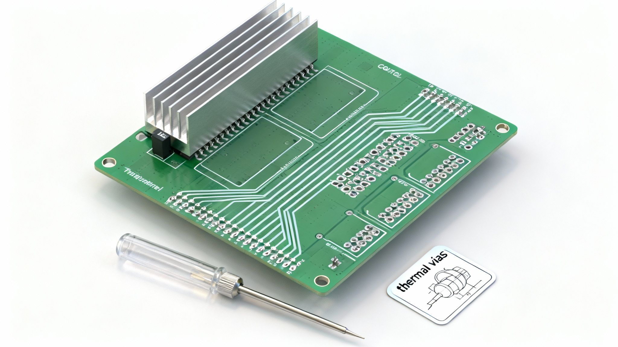
- Thermal Vias: An array of vias under a component’s thermal pad acts as a conduit, pulling heat from the top layer to large copper planes on inner or bottom layers.
- Large Copper Pours: Connecting power components to large copper planes spreads heat over a greater surface area, improving dissipation.
- Heatsinks: For any significant power application, a physical heatsink is essential. The PCB layout must be designed from the start to accommodate its mounting and ensure a solid thermal connection.
These design choices are critical in industrial settings, where motor control circuits are often packaged into Motor Control Centers (MCCs). This market reached USD 6.36 billion in 2023 and is projected to hit USD 11.94 billion by 2035, driven by automation in sectors like oil & gas. You can discover more insights about the growing motor control market on Research Nester. Proper thermal design is what separates a reliable product from a costly failure in these demanding environments.
Designing for Manufacturing and Testing
A brilliant motor control circuit that cannot be manufactured efficiently or tested reliably is a commercial failure. Design for Manufacturability (DFM) and Design for Test (DFT) are foundational disciplines that bridge the gap between engineering and production. Integrating these principles from the outset is what separates a smooth product launch from a cycle of costly rework, production delays, and poor yields.
This requires thinking like a production engineer during the design phase. Component placement must be optimized for automated pick-and-place machines, which means providing adequate clearance and using standardized footprints. Component tolerance selection must be made in consultation with the contract manufacturer to align design requirements with their real-world capabilities.
Implementing Practical DFM and DFT
A robust strategy embeds testability into the hardware from day one. When a board comes off the assembly line, its health must be verifiable quickly and accurately.
Non-negotiable considerations include:
- Accessible Test Points: Test points for critical signals like gate drive waveforms, current sense outputs, and power rails are your windows into the circuit's operation. They must be physically accessible to automated test jigs or a technician’s probes.
- Fiducial Marks: These optical alignment targets on the PCB are essential for automated assembly equipment, ensuring components are placed with high precision.
- Panelization Strategy: Boards are manufactured in multi-unit panels to reduce handling time. The panel design—including how boards are separated via breakaway tabs (mouse bites) or V-grooves—must be planned to avoid stressing components or traces.
This forward-thinking approach is more critical than ever. The global motor control IC market is projected to grow from USD 5.6 billion in 2024 to USD 15.4 billion by 2035. As these circuits incorporate AI for predictive maintenance and support fault-tolerant systems in aerospace and medicine, the pressure to achieve first-pass success is immense. You can learn more about motor control IC market findings from Future Market Insights.
A Real-World DFM/DFT Failure and Recovery
Overlooking manufacturability has significant financial consequences, as a medical device startup learned.
Problem: A new infusion pump controller was failing its end-of-line functional test at a 15% rate. The failures were intermittent, making root cause analysis nearly impossible and threatening to derail a critical product launch.
Diagnosis: Investigation traced the issue to the PCB layout. High-density component placement left no room for test probe access to the motor driver’s feedback loop. Technicians could not distinguish a component failure from a firmware bug or a bad solder joint without resorting to destructive, time-consuming manual testing.
Solution: The PCB was completely revised. The new design incorporated dedicated, accessible test pads for all critical analog and digital signals. This allowed an automated bed-of-nails tester to run a full diagnostic in under 30 seconds. For a detailed walkthrough of this kind of setup, see our guide on how to test a circuit board.
Outcome: The results were dramatic. The manufacturing team could instantly pinpoint the source of failures, which turned out to be a defective batch of current sense amplifiers. First-pass yield skyrocketed to 99.7%, rework costs were slashed by 90%, and the product launched on schedule, preventing a crippling delay.
Bringing in the Experts to Sidestep Common Pitfalls
Navigating the complexities of motor control circuit design is a high-stakes endeavor. A misstep in topology selection, component sourcing, firmware integration, or manufacturing readiness can lead to schedule slips, budget overruns, and project failure. Many organizations face a resource gap—their internal teams are stretched thin or lack the niche, cross-disciplinary expertise required to succeed on the first attempt.
A specialized development partner can be a game-changer. Instead of spending months hiring specialists or wrestling with complex EMI or firmware bugs, you can engage an on-demand team of vetted experts. This provides a direct solution to the root causes that stall complex engineering projects.
An expert partner provides a single, accountable program lead who coordinates the entire development lifecycle. This tight integration of firmware, hardware, and mechanical engineering ensures critical factors like Design for Manufacturability (DFM) are integrated from the beginning, not as an afterthought.
The result is a significant reduction in risk and a faster path to market. By leveraging a dynamic network of experts, you can move from prototype to production with confidence, knowing every aspect of the motor control circuit has been optimized for reliability and performance.
If you are facing a complex motor control challenge or need to get a stalled project back on track, the most effective next step is a targeted assessment. A short, high-value consultation can quickly identify critical risks and define a clear path to get your project to completion.
Frequently Asked Questions
When leading a motor control project, a few key questions consistently arise for engineering leaders and project managers. Here are actionable answers based on extensive field experience.
What Are the First Signs a Motor Control Circuit Project Is Failing?
Failure rarely manifests as a single event. It typically presents as a series of persistent technical issues: prototypes repeatedly failing under load, an inability to meet critical benchmarks for efficiency or thermal performance, and stubborn electromagnetic interference (EMI) that disrupts system behavior.
Another major red flag is a communication breakdown between the firmware and hardware teams, leading to integration chaos. The most critical sign of a deep-rooted problem is discovering late in the development cycle that a key component is unavailable or that your design is not manufacturable by your contract manufacturer. These issues almost always point to a failure in end-to-end planning.
How Do You Balance Cost Versus Performance in Component Selection?
This is where engineering meets business strategy. The solution lies in a rigorous trade-off analysis tied directly to your product’s market and, crucially, the quantifiable cost of failure.
For a high-volume consumer product, saving five cents on a MOSFET is a significant win when scaled across millions of units. However, for a low-volume, high-reliability medical device governed by ISO 13485 standards, selecting a more expensive component with a proven track record and superior thermal performance is the only responsible choice.
The key is to define your "cost of failure" and the non-negotiable "performance envelope" before starting component selection. This framework transforms the decision from a simple price comparison into a strategic risk assessment, ensuring your final bill of materials aligns with both budget and reliability targets.
Which Is More Critical to Get Right First: Hardware or Firmware?
This is a false choice. They must be developed in parallel, with constant, structured communication between the teams. One of the most common and costly failure modes is designing the hardware in a silo and then handing it off to the firmware team.
This sequential approach is a recipe for disaster. The firmware team may discover the selected MCU lacks the processing power for a required algorithm like Field-Oriented Control, or that the current sensing circuit lacks the necessary resolution for stable operation.
The only reliable path to first-pass success for a complex motor control circuit is a co-design methodology, where firmware requirements directly inform the hardware architecture from the project's inception.
Navigating the complexities of motor control circuit design requires deep, cross-disciplinary expertise. At Sheridan Technologies, we assemble on-demand teams of elite specialists to accelerate your development, mitigate risk, and ensure first-pass success.
If your project faces complex challenges, schedule a complimentary assessment to diagnose issues and define a clear path forward.