
Table of Contents
Design for Manufacturability (DFM) is not an academic exercise; it’s a critical risk-management discipline for bringing hardware to market. It is the practice of embedding manufacturing constraints and realities into the product design process from day one. DFM closes the gap between a validated prototype and a scalable, profitable product by forcing early collaboration between design, engineering, and production teams.
This approach preemptively diagnoses and resolves production issues before they can trigger costly late-stage redesigns, budget overruns, and catastrophic launch delays.
What Is Design For Manufacturability And Why Does It Matter?
At its core, DFM solves a single, ruinously expensive problem: the operational disconnect between design intent and production reality. In a traditional sequential workflow, engineering finalizes a design and “throws it over the wall” to manufacturing. This handoff frequently uncovers critical flaws: the design is too complex to assemble repeatably, requires exotic tooling, exceeds cost targets, or is physically impossible to produce at scale.
This triggers a reactive, high-stakes cycle of re-engineering, re-validation, and schedule slips that can cripple a product launch.

DFM inverts this model. It’s a disciplined methodology that forces engineers to consider the limitations and capabilities of the factory floor during the earliest architectural phases. By confronting critical questions upfront—”What is the optimal molding strategy for this enclosure?” or “Can this PCB layout be panelized for automated assembly?”—teams systematically de-risk the entire manufacturing lifecycle. This proactive approach has a direct, measurable impact on business outcomes, especially in regulated environments like medical devices (ISO 13485) and aerospace (DO-178C) where post-launch changes are prohibitive.
The Business Case for DFM
For executives, engineering leaders, and program managers, DFM is one of the most effective tools for controlling risk and ensuring project profitability. It directly mitigates the primary drivers of hardware project failure by focusing on tangible, defensible outcomes. Implementing a rigorous DFM process is a non-negotiable step in converting a prototype into a scalable product.
The business impacts are clear and measurable:
- Cost Reduction & Control: DFM is a primary lever for controlling COGS (Cost of Goods Sold). By simplifying designs and aligning them with standard manufacturing processes, companies typically reduce unit production costs by 20-30%. This avoids the exponential cost of late-stage engineering changes, which can inflate budgets by over 50%. Learn more about the financial impacts of DFM.
- Accelerated Time-to-Market: By eliminating redesign loops and streamlining production setup, DFM can reduce development timelines by months. In competitive markets, this speed translates directly to market share and revenue.
- Improved Reliability & Quality: A design optimized for its manufacturing process yields a more consistent product. This results in higher first-pass yields, fewer assembly errors, and a significant reduction in field failures, warranty claims, and recall risk.
Strategic Impact Analysis: DFM Adoption vs. Traditional Workflow
The strategic value of DFM is most evident when contrasted with a traditional, sequential development workflow. The following table provides a clear breakdown of the business implications for decision-makers.
| Metric | Traditional Sequential Workflow | DFM-Integrated Workflow |
|---|---|---|
| Development Cycle | Linear, with late-stage redesign loops causing significant delays. | Concurrent, with manufacturing feedback integrated early and often. |
| Production Cost | Higher unit costs due to inefficient processes, specialized tooling, and manual assembly. | Lower unit costs driven by design simplification, process optimization, and automation. |
| Product Risk | High risk of manufacturability issues discovered late, leading to budget overruns and schedule slips. | Reduced risk through early identification and mitigation of potential production failures. |
| Supply Chain | Fragile, often dependent on single-source, highly specialized suppliers. | Resilient, utilizing standardized components and common manufacturing processes. |
Ultimately, the choice is between a reactive process governed by unforeseen, costly surprises and a proactive strategy architected for predictability, scalability, and profitability. DFM is not just about simplifying factory operations; it’s about building a more resilient and competitive business.
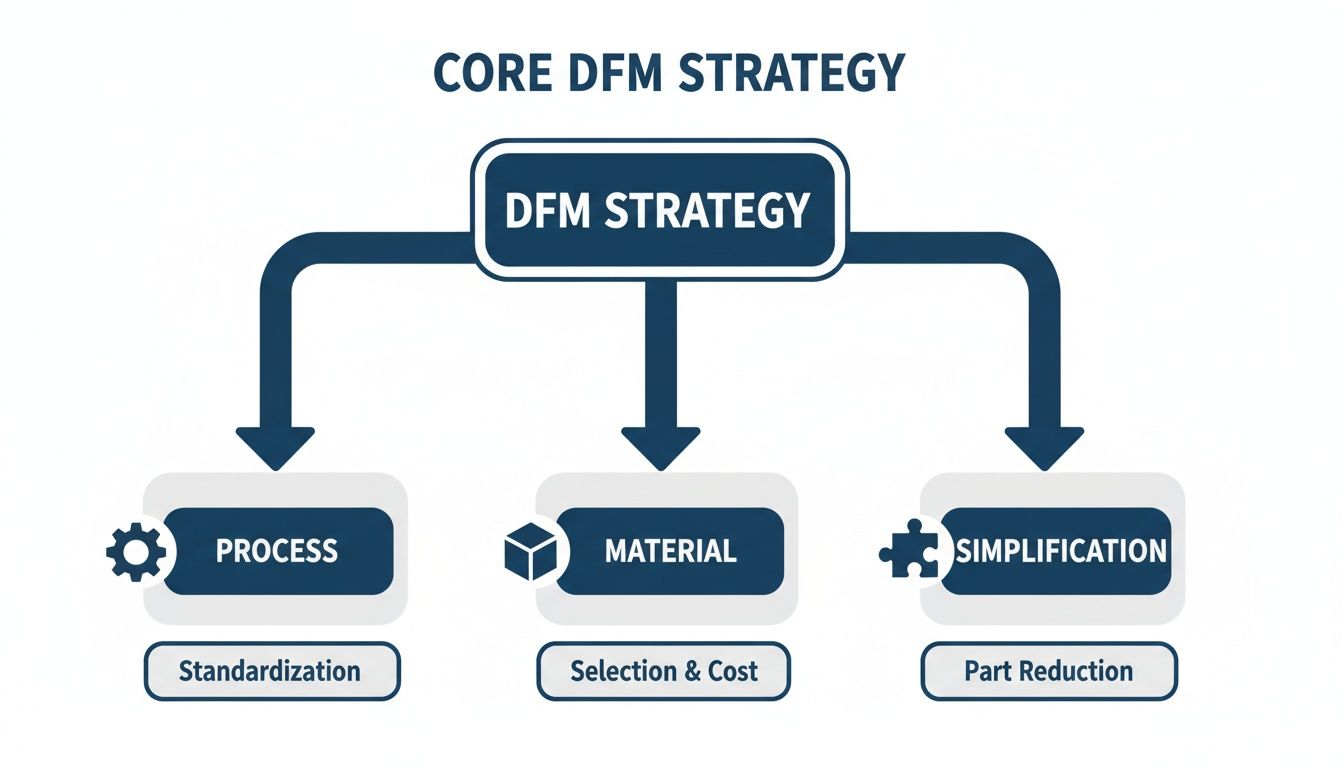
The Core Pillars of a Robust DFM Strategy
An effective Design for Manufacturability strategy is a systematic framework that links every design decision to a real-world production outcome. It moves beyond checklists to instill a disciplined approach for de-risking production, controlling costs, and accelerating market entry. Neglecting these fundamentals is a direct path to budget overruns and missed deadlines.
A robust DFM strategy is built on four core pillars: process selection, material specification, design simplification, and component standardization. Each represents a critical decision point where an engineering choice has cascading effects throughout the entire manufacturing lifecycle.
Process and Material Selection
The initial decision of selecting the manufacturing process—such as injection molding for a high-volume enclosure versus CNC machining for a low-volume medical device prototype—is arguably the most impactful. The chosen process dictates fundamental design rules, including achievable tolerances, surface finishes, and geometric possibilities.
This decision is inextricably linked to material selection. A material may offer ideal performance characteristics, such as the biocompatibility of PEEK for a surgical instrument, but present significant machining challenges or prohibitive costs. The key is to identify the intersection where material properties, manufacturability, and cost align without compromising product function.
For example, a design may specify an exotic alloy for its strength-to-weight ratio. However, if this alloy is also highly abrasive, it will accelerate tool wear, reduce machining speeds, and potentially increase the per-unit cost by 30-40%. A proper DFM analysis would flag this tradeoff and prompt an evaluation of alternative materials that meet 95% of performance requirements but can be machined five times faster. DFM also extends to lifecycle considerations, including responsible waste management and programs for industrial plastic recycling.
Design Simplification and Part Consolidation
Complexity is the primary antagonist of manufacturability. Each additional part in an assembly introduces cascading costs and potential failure points: more tooling, increased handling, additional assembly labor, and another quality inspection step. A foundational tenet of DFM is aggressive simplification.
The most reliable component is the one that isn’t there. A primary goal of DFM is to challenge every feature and part, asking if its function can be integrated elsewhere or eliminated entirely.
Scenario: A medical diagnostic device is initially designed with a chassis comprising 12 discrete machined and sheet metal parts.
Problem: High assembly labor cost, tolerance stack-up issues, and multiple points of failure.
DFM Solution: Redesign the chassis as two consolidated injection-molded parts.
Outcome:
- Reduced Assembly Time: Eliminating fasteners and manual alignment slashes labor costs and increases throughput.
- Improved Structural Integrity: A single molded part provides superior rigidity and dimensional consistency compared to a fastened assembly.
- Lower Per-Unit Cost at Scale: While initial tooling for injection molding is a capital expense, the per-unit cost at volume is a fraction of a complex multi-part assembly.
This strategic part consolidation transforms a design from a collection of components into an integrated, optimized system.
Standardization of Components and Features
The final pillar is standardization. Relying on custom fasteners, proprietary connectors, or non-standard feature dimensions introduces supply chain fragility and drives up costs. An effective DFM strategy mandates the use of common, off-the-shelf components wherever feasible.
This principle extends to design features. For instance, standardizing on a limited set of corner radii for machined parts enables the use of common tooling, reducing machine setup times and simplifying CAM programming. This seemingly minor detail avoids the need for specialized, fragile, small-diameter end mills that require slower cutting speeds. By establishing and enforcing a library of standard components and features, engineering teams embed predictability and efficiency into the product’s DNA.
Applying DFM Across Engineering Disciplines
DFM is not a siloed function but a holistic philosophy that must permeate all engineering disciplines. A mechanical design flaw can render a PCB unusable, and a firmware oversight can brick thousands of units on the factory floor. One of the most common failure modes is optimization within disciplines without cross-functional review, leading to late-stage integration failures that derail schedules and budgets.
Mechanical Engineering DFM
For mechanical engineering, DFM focuses on the physics of fabrication. Minor geometric decisions have significant impacts on tooling cost, production speed, and part quality.
- Tolerances: The guiding principle is to specify the loosest tolerances that still achieve the required function. Unnecessarily tight tolerances—for instance, anything below ±0.002″ (±0.05 mm) on a non-critical feature—can increase machining costs by 50% to 500% by requiring specialized equipment and intensive quality control.
- Draft Angles: For injection molding, this is a non-negotiable requirement. Omitting adequate draft (typically 1-3 degrees) will cause parts to stick in the mold, resulting in cosmetic defects, part damage, and increased cycle times.
- Uniform Wall Thickness: Significant variations in wall thickness in molded parts lead to differential cooling rates, causing warpage and internal stress. Maintaining uniform thickness is critical for dimensional stability.
- Material Flow: In molding, improper gate and runner design can lead to cosmetic defects like weld lines or structural issues like sink marks and voids, compromising the part’s integrity.
Electronics and PCB Design DFM
For electronics, DFM for Printed Circuit Boards (PCBs) ensures a design can be fabricated and assembled at high yield. This requires a deep understanding of the contract manufacturer’s (CM) process capabilities. For a detailed analysis, see our guide on PCB design for manufacturing.
A PCB design can pass every electrical rule check (ERC) and still be completely unmanufacturable. DFM is the bridge between a theoretically correct schematic and a board that can be reliably assembled by automated equipment.
Key DFM checks for electronics:
- Component Selection: Avoid single-source or near end-of-life components. Prioritize parts with long lifecycles and multiple qualified suppliers to mitigate supply chain risk.
- Panelization Strategy: An inefficient panel layout wastes expensive laminate material and increases handling time, directly impacting unit cost. The layout must be optimized for the CM’s specific pick-and-place and test equipment.
- Solderability and Clearances: Insufficient spacing between components can lead to solder bridging during reflow. Incorrect solder mask clearances can cause shorts or weak solder joints, leading to field failures.
- Design for Test (DFT): Incorporating test points for critical signals into the layout is essential for automated in-circuit testing (ICT). Without DFT, diagnosing production failures becomes a slow, manual, and expensive process.
Firmware DFM: The Often-Overlooked Discipline
Firmware is the most frequently neglected aspect of DFM, yet a failure here can be as costly as a mechanical defect. A batch of 10,000 devices bricked during factory programming represents a catastrophic financial and logistical failure.
- Production Programming Interface: The design must include a fast, reliable interface (e.g., SWD, JTAG) for initial firmware flashing. A slow or unreliable method adds significant cycle time and cost to every unit.
- Secure In-Field Updates: A robust, failsafe bootloader is critical. A fragile update mechanism that can be interrupted by power loss creates a risk of bricking devices in the field, leading to costly recalls and warranty claims.
- Unique Device Identification: Every device must be programmable with a unique serial number or ID during manufacturing for traceability, field diagnostics, and fleet management.
- Manufacturing Test Modes: Implement a dedicated firmware mode that allows factory test fixtures to rapidly exercise and verify all peripherals (sensors, radios, motors). This automates the final functional test, ensuring every shipped unit is fully operational.
DFM Discipline-Specific Priority Checklist
The table below summarizes the top DFM priority for each discipline and the common failure mode that results from its neglect.
| Discipline | Top DFM Priority | Potential Failure Mode if Ignored |
|---|---|---|
| Mechanical | Material Selection & Process Compatibility | Warping, cracking, or cosmetic defects due to mismatched material properties and manufacturing process (e.g., wrong plastic for injection molding). |
| Electronics | Component Sourcing & Availability | Production line shutdown because a critical, single-source component becomes unavailable, forcing a costly and time-consuming redesign. |
| Firmware | Robust Programming & Test Automation | A batch of thousands of units are bricked during initial factory flashing due to an unreliable programming interface or untested firmware. |
A successful DFM strategy hinges on communication and foresight. When mechanical, electronics, and firmware engineers understand the downstream impact of their decisions on the factory floor, a collection of well-designed parts becomes a truly manufacturable product.
From Problematic Prototype to Production Success Story
Theory is useful, but a real-world scenario demonstrates the tangible business impact of Design for Manufacturability. The following case illustrates how DFM can transform a high-risk prototype into a scalable, profitable product.
Problem: An Unscalable R&D Triumph
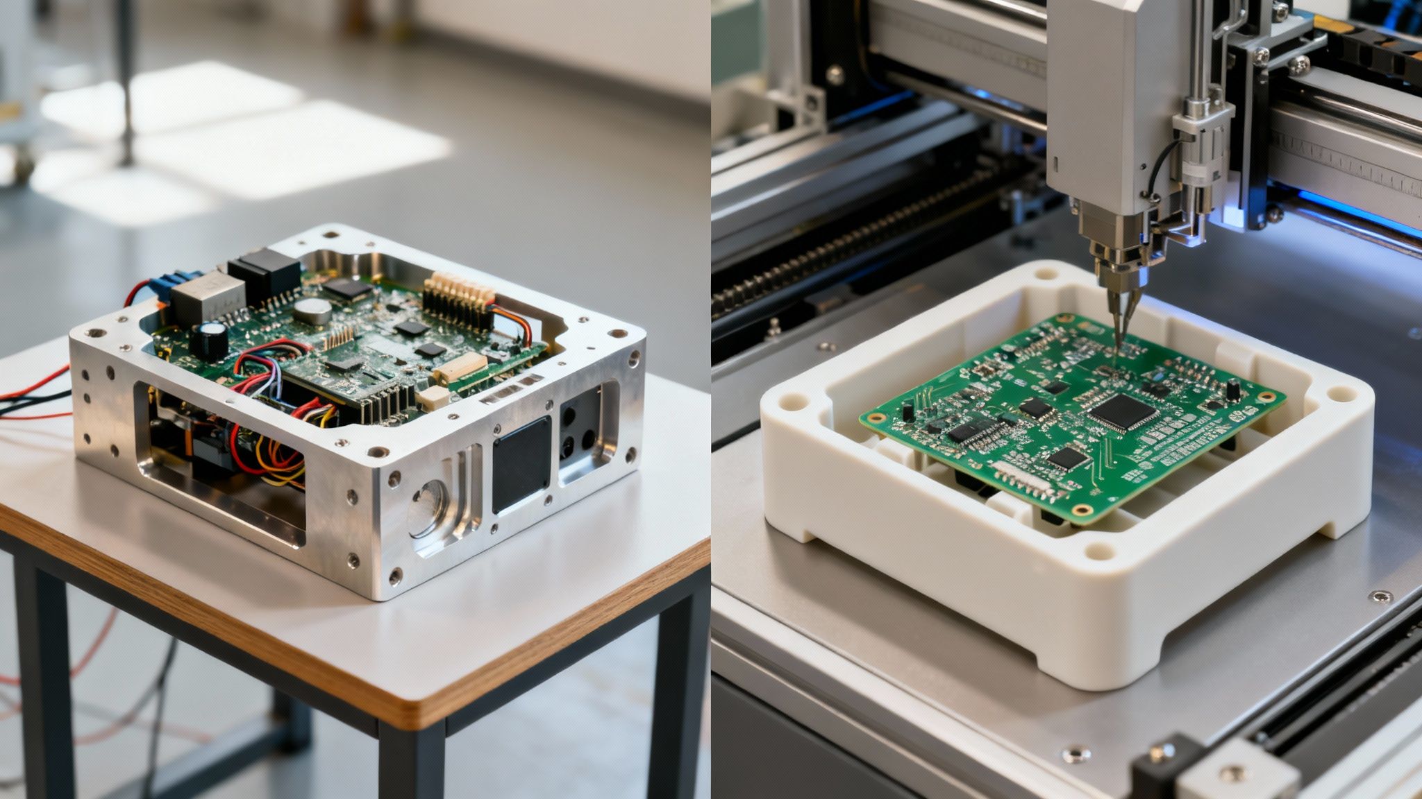
A venture-backed robotics startup develops a prototype for an autonomous warehouse robot. The prototype performs flawlessly in the lab. Focused on speed, the team used custom-machined aluminum for the chassis and a densely packed PCB hand-assembled by their lead engineer. The design secured a pilot program with a major retailer, requiring delivery of 500 units in four months. The prototype, a success in R&D, was now a production liability.
Diagnosis: Unmanufacturable at Scale
RFQs sent to contract manufacturers (CMs) returned with stark feedback: the current design was not manufacturable at scale within the required cost and time constraints.
Key flaws identified by the CMs:
- Prohibitive Machining Costs: The multi-part, CNC-machined enclosure cost over $800 per unit to produce, eliminating any potential profit margin.
- Manual Assembly Bottleneck: The hand-soldered PCB required eight hours of skilled labor per unit, making the production timeline impossible and introducing significant quality control risks.
- Latent Thermal Failures: The densely packed PCB created thermal hotspots that did not manifest in short lab tests but caused critical system failures during the extended burn-in testing required for production units.
Solution: A Strategic DFM Intervention
The startup engaged a manufacturing partner to conduct a full DFM audit. This was not a minor revision but a strategic re-engineering of the product for mass production.
Targeted interventions included:
- Mechanical Redesign for Injection Molding: The enclosure was redesigned as a single, consolidated part optimized for high-pressure plastic injection molding. This required careful analysis of draft angles, uniform wall thickness, and material selection to meet structural requirements.
- PCB Layout Optimization for Automation: The PCB was re-laid out for automated pick-and-place assembly. This included optimizing component spacing, panelizing the board for the CM’s equipment, adding test points for automated quality control, and designing in proper thermal pathways to dissipate heat.
- Component and Fastener Standardization: The bill of materials (BOM) was rationalized. Dozens of unique screw types were replaced with a handful of standard fasteners, simplifying inventory management and streamlining final assembly.
The pivotal decision was matching the design to the correct manufacturing process. Shifting from CNC machining to injection molding was the key that unlocked dramatic cost and time savings. Learn more about the specific constraints of designing for injection molding.
Outcome: Accelerated Market Entry and Profitability
The DFM overhaul produced immediate and significant business results:
- The per-unit production cost was reduced by 40%, primarily due to the switch to injection molding.
- Final assembly time was cut by over 60% due to the optimized PCB and standardized hardware.
- The redesigned product passed all reliability and thermal stress tests on the first production run.
This first-pass success enabled the startup to meet its delivery deadline, enter the market three months ahead of its revised schedule, and secure a follow-on contract. This scenario is not an anomaly. Today, 65% of venture-backed hardware teams report achieving a 50% faster prototype-to-production timeline by integrating DFM. Discover more insights about these OEM practices. DFM is a critical business process for converting technical innovation into a commercially viable product.
Navigating Common DFM Pitfalls and Tradeoffs
Effective DFM is not about achieving a theoretical optimum; it is a discipline of managing tradeoffs between cost, performance, reliability, and scalability. This is where experienced engineering leaders add the most value.
A common failure mode is over-optimizing for a single variable, typically cost, at the expense of others. In regulated industries, this can be catastrophic. For a medical device governed by ISO 13485, selecting a cheaper, less-vetted component to save $0.10 per unit introduces a disproportionate risk of field failures, patient harm, and recalls. Similarly, in aerospace systems under DO-178C, a design change that simplifies manufacturing but compromises deterministic behavior could jeopardize certification. The objective is not merely cost reduction but engineering a balanced design that meets all functional, reliability, and regulatory requirements within an acceptable cost envelope.
The Danger of Incomplete Analysis
Another common pitfall is conducting a DFM analysis with a narrow focus on part fabrication while ignoring assembly, test, and serviceability. A part may be perfectly designed for injection molding, but if that design complicates final assembly, the total cost and failure rate will increase.
This myopia manifests in predictable ways:
- Ignoring Assembly: Designing an enclosure that requires a complex, non-obvious sequence of steps, inflating labor time and creating opportunities for error.
- Neglecting Testability: Failing to include accessible test points on a PCB, converting a 30-second automated test into a 10-minute manual troubleshooting session.
- Overlooking Downstream Processes: Forgetting the full product lifecycle. For example, failing to consider secure data destruction requirements for onboard storage can create significant compliance issues at end-of-life.
Supplier and Process Constraints
Designing a product that is locked into a specific manufacturing process or a single-source supplier is a strategic error. A design optimized for low-volume CNC machining may be entirely unsuitable for high-volume injection molding, forcing a costly redesign just as market demand accelerates.
Single-sourcing a critical component, such as a microcontroller, creates extreme supply chain fragility. A single factory disruption or allocation issue can halt production for months.
DFM gained prominence in the 1980s as Japanese automakers adopted concurrent engineering, bringing manufacturing experts into the design process early. This led to a reported 50% reduction in defect rates and a 60% reduction in rework. In the medical device industry, DFM principles like Poka-yoke (error-proofing) have driven field failure rates below 1%.
To mitigate these risks, leaders must implement multi-objective optimization. This involves a rigorous supplier qualification process that prioritizes components with multiple sources and stable lead times. It also demands a forward-looking process strategy, such as prototyping with machining but designing the part from day one with features like draft angles to ensure a seamless transition to molding.
Integrating DFM Into Your Development Process
Integrating DFM is not about adding another bureaucratic checkpoint; it’s about embedding manufacturability as a core competency within the engineering culture. The goal is to shift DFM from a theoretical concept to a driver of tangible business results: reduced risk, faster timelines, and improved profitability.
A powerful starting point is a retrospective audit. Analyze a product already in production through a DFM lens. This exercise almost always reveals immediate cost-saving opportunities and provides concrete data to build the business case for broader DFM adoption.
Phased Implementation Strategy
Formal DFM reviews should be integrated as critical gates within your new product introduction (NPI) process.
- Gate 1: Concept & Architecture Review: At this early stage, confirm foundational choices. Is the design aligned with the intended volume manufacturing process (e.g., designing for injection molding even while prototyping with 3D printing)? Have high-risk components and material availability been assessed?
- Gate 2: Detailed Design Review: This is a deep-dive analysis of CAD models and schematics. The review should use a checklist to identify specific DFM violations, such as missing draft angles, features that are difficult to machine, or a PCB layout that cannot be efficiently panelized. This is the last opportunity to fix problems cheaply.
- Gate 3: Pre-Tooling Release: This is the final validation with your manufacturing partner, confirming that all prior feedback has been implemented before committing capital to hard tooling or production line setup.
The ultimate objective is to foster a culture where design engineers consult with manufacturing experts—whether internal teams, a Contract Manufacturer (CM), or a specialized firm—from the earliest stages of conceptualization.
This early and continuous engagement is the single most effective way to de-risk a hardware product launch.
Common Questions We Hear About DFM
As product leaders and engineers implement Design for Manufacturability, several practical questions consistently arise.
When Is the Right Time to Introduce DFM?
The optimal time is at project inception. The greatest leverage on final product cost, quality, and timeline occurs during the initial architectural phase. Early decisions regarding materials, core components, and assembly strategy have cascading effects. If DFM is delayed until the design is “feature complete,” the most significant cost drivers are already locked in, and the process becomes a reactive, less effective exercise in damage control.
How Is DFM Different from Design for Assembly?
This is a common point of confusion. Design for Assembly (DFA) is a critical subset of the broader DFM discipline.
DFA focuses specifically on optimizing the physical process of putting the product together. It addresses questions like, “How can we reduce part count and fastener types?” or “Can this part be designed to prevent incorrect installation?” Its scope is the final assembly line.
DFM encompasses the entire ecosystem required to deliver parts to that assembly line:
- Part Fabrication: Can individual components be molded, machined, or stamped efficiently and repeatably?
- Finishing & Post-Processing: Do the specified surface finishes add unnecessary cost and process steps?
- Testing: Is the PCB designed with accessible test points to enable automated in-circuit testing?
- Supply Chain & Logistics: Are components standardized and sourced from multiple suppliers to build a resilient supply chain?
In short, while DFA refines the final assembly, DFM optimizes every preceding step required to produce and deliver the constituent parts.
Can DFM Be Applied to an Existing Product?
Yes. Applying DFM principles to a product already in production is a common practice known as value engineering. While it lacks the high leverage of early-stage implementation, value engineering can yield significant and immediate cost reductions.
The process involves a systematic analysis of an existing design to identify opportunities for cost reduction, yield improvement, or enhanced reliability. This might involve consolidating multiple parts into a single component, switching to a more scalable manufacturing process (e.g., from machining to die-casting), or qualifying alternative components to mitigate supply chain risk. The outcome is a measurable reduction in unit cost and an increase in production throughput for all future builds.
Integrating DFM is the most effective way to de-risk a product launch and ensure a successful manufacturing ramp. The expert team at Sheridan Technologies specializes in weaving manufacturability into every phase of development, from initial architecture to final production handoff.
Schedule a consultation to assess your project’s manufacturing readiness.