Table of Contents
Developing a mechatronic or robotic product with siloed mechanical, electrical, and firmware teams is a recipe for integration failure, costly rework, and blown schedules. When these disciplines don’t communicate from day one, critical system-level flaws only surface late in the EVT or DVT phases, forcing expensive redesigns when the pressure to ship is highest. The stakes are simple: ignore a unified design approach, and you risk delivering an unreliable product late and over budget.
This guide is for engineering leaders, program managers, and lead engineers tasked with delivering a complex mechatronic system. It provides an operationally-focused framework for de-risking the development lifecycle, from architecture to production. This is not for academic R&D; it’s for teams building real-world products who need to align technical execution with business outcomes like time-to-market and manufacturing readiness.
Here’s what you’ll learn:
- How to identify critical system integration points during initial architecture to prevent late-stage surprises.
- How to structure a phased development process (EVT/DVT/PVT) that systematically validates the design for reliability and manufacturability.
- How to anticipate and mitigate common failure modes in control loops, sensor integration, and firmware before they derail your program.
Breaking Down the Architecture of a Modern Mechatronic System
A modern mechatronic and robotics system isn’t an assembly of parts; it’s an integrated ecosystem where the mechanical frame, electronic nervous system, and software brain are deeply intertwined. Designing these elements in isolation guarantees integration pain. To build a system that is testable, reliable, and manufacturable, you must start with a cohesive, system-level architecture.
This means breaking the system down into core subsystems, understanding their dependencies, and making critical trade-offs before a single PCB is ordered. The best way to approach this is from the physical world inward—from the sensors and actuators that interact with the environment, to the electronics that drive them, and finally to the embedded intelligence that orchestrates it all.
The Core Subsystems and How They Talk to Each Other
Let’s ground this in a real-world scenario: designing an autonomous warehouse robot. This system must navigate a dynamic environment, manipulate packages with precision, and coordinate with a central fleet manager. Its operational success hinges on the seamless integration of its core subsystems.
- Mechanical Structure: The chassis, drivetrain, and manipulator arm. These define the robot’s physical capabilities—payload, speed, and durability. Decisions on materials and gearbox selection directly impact power requirements and control system tuning.
- Sensors and Actuators: The robot’s senses and limbs. LiDAR, cameras, and encoders provide situational awareness and state feedback. Motors, servos, and grippers execute physical commands. Sensor choice directly impacts the complexity of the firmware’s signal processing and control algorithms.
- Electronics and Power: The circulatory and nervous system. This includes the analog front-end for sensor signal conditioning, the power distribution network, and the motor drivers that deliver precise current. For details, see our analysis of motor control circuit design.
- Embedded Controller: The brain of the operation. A microcontroller (MCU) or microprocessor (MPU) runs the real-time control loops, processes sensor data, and makes decisions.
- Firmware and Software: The logic that brings the hardware to life. This spans from low-level peripheral drivers to high-level pathfinding algorithms and communication protocols.
This map illustrates how distinct engineering fields must converge to create a successful product.
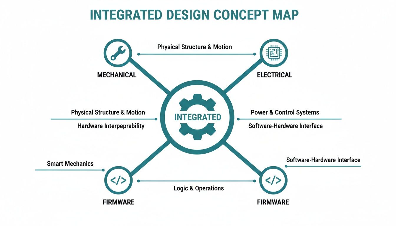
The key takeaway is that mechanical limits, electrical capabilities, and firmware logic aren’t separate problems. They are interconnected variables in a single system equation that must be solved holistically. A unified approach is a core principle of our engineering design services.
The Critical Tradeoffs You Have to Make Early
Architectural decisions made on day one have cascading effects on cost, reliability, and time-to-market. Your team must resolve these trade-offs before committing to a design path.
A classic failure mode is selecting a processor or communication bus that excels at one task but cannot meet the system’s overall real-time demands, forcing a costly redesign deep into the development cycle.
Key architectural decisions include:
- Centralized vs. Distributed Control: Should one powerful processor manage everything, or should smaller, dedicated microcontrollers handle specific tasks like motor control? A distributed approach can improve modularity and fault tolerance but increases communication complexity.
- Processor Selection (MCU vs. MPU): The choice depends on processing needs and real-time constraints. MCUs are ideal for hard real-time control loops where deterministic execution is non-negotiable. MPUs are necessary for running complex algorithms or a high-level operating system like Linux.
- Communication Protocols: Not all protocols are equal. For time-sensitive control loops between controllers, sensors, and actuators, a deterministic protocol like CAN bus or EtherCAT is often required to guarantee message delivery. For non-critical telemetry, standard Ethernet or Wi-Fi may suffice.
Because embedded software is the glue holding modern systems together, solid software documentation best practices are essential for long-term maintainability. These early architectural choices form the blueprint for a system that is not just functional but also testable, scalable, and manufacturable.
The Development Workflow From Concept to Production
Moving a complex mechatronic or robotic system from concept to a reliable product is a phased journey, not a linear sprint. For program managers and engineering leads, this workflow is the blueprint for managing complexity and systematically de-risking the program before committing to expensive production tooling.
Each stage builds on the last, validating the design against increasingly stringent criteria. The goal is to identify and resolve issues early, when the cost of change is lowest, long before they can disrupt a manufacturing run.
From EVT to PVT: The Phased Gate Process
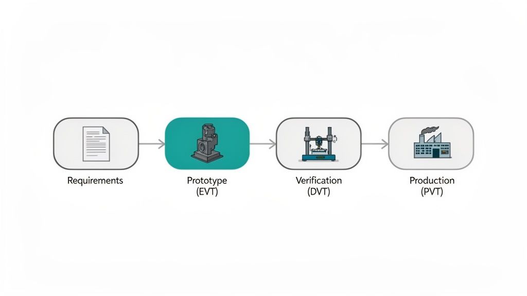
The path from a single prototype to thousands of units is governed by three critical gates: EVT, DVT, and PVT. These are formal quality checkpoints that prevent an immature design from moving forward prematurely.
- EVT (Engineering Validation Test): The “does it work?” phase. Using a small number of hand-built units, the focus is on validating core architecture and functionality. You’re testing your biggest assumptions—does the motor have enough torque? Can the power supply handle peak current draw? The goal is to prove the fundamental design is viable.
- DVT (Design Validation Test): The question becomes, “does it work reliably and meet all specifications?” Using production-intent parts and processes, the design is subjected to comprehensive environmental testing (temperature, vibration), EMC/EMI compliance, and accelerated life testing to find its breaking points.
- PVT (Production Validation Test): Finally, you ask, “can we build this at scale?” This phase validates the manufacturing line itself. You confirm yield, cycle time, and quality control processes to ensure you can consistently produce products that meet spec.
Navigating this transition is a significant challenge. For a deeper look, see our guide on managing the prototype-to-product journey. This structured approach is what separates systems that ship from those that remain stuck in “development hell.”
The Power of Hardware-Firmware Co-Design
A common failure mode is treating firmware development as an activity that begins after the first hardware prototypes arrive. This is a recipe for delay. High-performing teams run hardware and firmware development in parallel from day one.
Hardware-in-the-loop (HIL) testing and simulation are critical enablers. By creating a virtual model of the hardware, the firmware team can write and debug the majority of their code against simulated sensors and actuators. This transforms weeks of painful on-hardware debugging into a few days of focused integration.
When the first EVT boards arrive, the firmware is already mature. The team can immediately focus on system-level integration challenges rather than chasing basic functionality bugs, effectively compressing the project timeline.
Verification Strategy and Change Control
Your verification plan is the backbone of the DVT phase. It is not a generic checklist; it’s a formal document that maps every system requirement to a specific test case with unambiguous pass/fail criteria. This isn’t about “kicking the tires”—it’s about systematically proving that the design meets every requirement.
Testing will uncover issues, and changes are inevitable. To prevent chaos, a disciplined Engineering Change Order (ECO) process is essential. An ECO provides a formal system for proposing, reviewing, approving, and documenting any design modification. It ensures all stakeholders understand the impact on cost, schedule, and performance before a change is implemented, preventing uncontrolled tweaks that lead to regressions and stall the project.
Where the Stakes Are Highest: Mechatronics in the Real World
The principles of mechatronics and robotics are not a one-size-fits-all formula. The blend of mechanical, electrical, and software engineering is constant, but the application context changes everything. Design choices, regulatory hurdles, and business risks differ dramatically across high-stakes industries.
A design that works in a clean, climate-controlled factory would fail catastrophically in a harsh agricultural environment. Understanding these contextual demands is key to making smart architectural decisions that align with business outcomes like regulatory approval, operational uptime, and market acceptance.
Industrial Automation and Collaborative Robotics
The modern factory floor is a masterclass in mechatronics. The rise of collaborative robots (“cobots”) designed to work alongside humans has placed an intense focus on system reliability and functional safety. A failure is not just a production delay; it’s a potential safety incident.
This environment demands a focus on:
- Failsafe Actuator Control: Motors and actuators require redundant braking systems and precise torque sensing to prevent unexpected movements that could cause injury.
- Deterministic Communication: Real-time industrial protocols like EtherCAT are often non-negotiable. Safety-critical commands must be executed with predictable, low latency.
- Certified Safety Logic: Control systems must often meet rigorous functional safety standards like ISO 13849, which defines performance levels for safety-related control systems.
Industrial robot installations have more than doubled in the last decade, a trend driven by the immense value of reliable, safe automation.
Medical Devices and Surgical Robotics
Nowhere are the stakes higher than in medical technology. For a surgical robot, precision and reliability are life-or-death requirements. A microscopic positioning error or a transient software glitch could have devastating consequences for a patient.
The entire field is governed by strict regulatory frameworks that demand rigorous process and documentation.
The core challenge is not just building a device that works, but creating a verifiable, auditable trail of evidence that proves it is safe and effective. Every design choice must be justified and documented.
Key design considerations include:
- Stringent Regulatory Compliance: Systems must adhere to standards like IEC 62304 for the software lifecycle and ISO 13485 for the quality management system.
- Sub-Millimeter Precision: This requires high-resolution encoders, backlash-free gearboxes, and control loops that can compensate for mechanical imperfections in real time.
- Extreme Reliability and Redundancy: Critical subsystems, from power supplies to processors, often require full redundancy to ensure the system can fail gracefully without harming the patient.
Agricultural Technology in Harsh Environments
Designing an autonomous tractor or robotic harvester introduces a different set of challenges. These machines must operate reliably for thousands of hours while enduring constant vibration, extreme temperatures, moisture, and dust.
The lessons learned in developing ruggedized systems for manufacturing and industrial applications often translate directly to other punishing environments.
Here, the engineering focus shifts to ruggedization and resilience:
- Environmental Sealing: Enclosures, connectors, and sensor housings often require an IP67 rating or higher to protect sensitive electronics from water and dust ingress.
- Vibration and Shock Tolerance: Components must be selected and mounted to withstand a lifetime of mechanical shock and vibration. This often involves potting electronics and using robust, locking connectors.
- Wide Temperature Component Selection: All electronic and mechanical components must be rated for a wide operational temperature range, from freezing conditions to scorching afternoon heat.
In each of these industries, a successful mechatronic system is born from a deep understanding of the operational context and its unique risks. The right technical choices are those that directly mitigate these high-stakes challenges, ensuring the final product is safe, reliable, and ready for the real world.
Common Failure Modes and How to Mitigate Them
Even well-planned mechatronic or robotic system developments encounter technical issues. The difference between a successful project and one that stalls is anticipating common problems and embedding mitigation strategies into your design process from the start.
Waiting for these issues to surface during integration leads to late-stage discoveries that detonate schedules and budgets. The key is to move from reactive bug-fixing to a proactive culture of designing for reliability and testability.
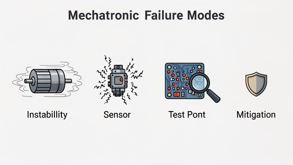
Unstable Control Loops and Actuator Jitter
A classic sign of trouble: a robot arm oscillates wildly, or a motor overshoots its target. This physical instability almost always points to a poorly tuned control loop, where the firmware is reacting improperly to sensor feedback.
This is a textbook failure of siloed engineering. The root cause is a disconnect between the clean digital control algorithm and the messy physical reality of the mechanical system—its inertia, friction, and backlash. The firmware team cannot solve this in isolation.
How to Fix It:
- System Identification: Before writing control code, characterize the physical system (the “plant”). Measure its actual response to known inputs to create an accurate mathematical model.
- Model First, Tune Later: A Proportional-Integral-Derivative (PID) controller is a mechatronics workhorse, but tuning it by trial and error on hardware is inefficient and risky. Use simulation tools like MATLAB/Simulink to tune gains against your model before deploying code to the target.
- Implement Anti-Windup Logic: When a motor is at its maximum output but the system has not reached its setpoint, the integral term of a PID controller can accumulate a large error, causing significant overshoot later. Anti-windup is a standard technique that prevents this “integral windup,” ensuring a smoother response.
Sensor Noise and Inaccurate Readings
A control system is only as good as its sensor data. When sensor readings are noisy, intermittent, or environmentally compromised, system behavior becomes unpredictable. An autonomous vehicle might misjudge an obstacle, or a robotic gripper might miss its target.
This is a classic electromechanical integration problem. The cause could be electrical noise coupling into analog signal lines, an inappropriate sensor for the environment, or an inadequate firmware filtering algorithm.
How to Fix It:
- Signal Integrity Analysis: Don’t just trust the data in your firmware. Use an oscilloscope to probe sensor outputs at the microcontroller’s input pins while the system is running. Look for high-frequency noise, voltage droops, or other anomalies.
- Analog and Digital Filtering: Use a two-pronged approach. Implement simple low-pass filters in hardware to eliminate high-frequency noise before it’s digitized. In firmware, use algorithms like Kalman filters or moving averages to further clean up the data.
- Proper Grounding and Shielding: This is non-negotiable. Use a clean ground plane for sensitive analog components. Use shielded cables for sensor lines running near noise sources like motor drivers or switching power supplies.
Firmware Faults and System Lockups
In a complex system, it’s not a question of if firmware will encounter an unexpected state, but when. A subtle memory leak, a race condition in a real-time operating system (RTOS), or a sensor failure can cause the entire system to lock up.
For a medical device or an industrial robot, this is a critical safety failure.
The most dangerous bugs are those that manifest only after hundreds of hours of runtime in the field. Robust firmware must be designed with the assumption that faults will occur and include mechanisms to recover gracefully.
Essential Reliability Patterns:
- Watchdog Timers: This is the firmware’s dead-man’s switch. A watchdog is a hardware timer that the application must periodically reset or “pet.” If the firmware locks up and fails to pet the watchdog, the timer expires and triggers a system reboot, forcing a recovery.
- Brownout Detection (BOD): A momentary dip in supply voltage can corrupt memory and cause erratic CPU behavior. BOD circuitry monitors the voltage rail and holds the processor in a safe reset state if it drops below a safe threshold, preventing the execution of corrupted code.
- Fault Containment: Modern microcontrollers often include a Memory Protection Unit (MPU). Use it to create isolated memory regions for different software tasks. This can prevent a fault in a non-critical task (like communications) from corrupting memory used by a critical one (like motor control).
Your Action Plan for Production Readiness
Moving a complex mechatronic and robotics system from proof-of-concept to a shippable product is where execution matters most. This section provides a practical checklist to assess your program’s health and expose blind spots that can derail a production launch.
Use this as a tool for your next project review. Be brutally honest about where you stand. The goal is not to build a single prototype that works on a lab bench; it is to deliver a reliable, manufacturable, and profitable product. Every decision must be made with a smooth production ramp in mind.
The Production Readiness Checklist
This list covers the high-leverage areas where teams most often get into trouble. A “no” or “partially” on any of these questions indicates a major program risk that requires immediate attention.
1. Is Your System Architecture Documented and Defensible?
This is about building institutional memory and eliminating ambiguity.
- Decision Log: Do you maintain a living document that captures the why behind key architectural decisions (e.g., MCU selection, bus architecture, power topology)? This artifact is critical for onboarding and long-term maintenance.
- Interface Control: Are the interfaces between mechanical, electrical, and firmware subsystems formally defined in an Interface Control Document (ICD)? Ambiguity here is a primary cause of late-stage integration failures.
- Requirements Traceability: Can you trace every top-level product requirement to a specific design choice in hardware or a function in firmware? Without this, your verification plan is built on guesswork.
2. Do You Have a Comprehensive Verification and Validation Plan?
A plan that exists only in someone’s head is not a plan.
- Test-to-Requirement Mapping: Does every system requirement have a corresponding test case in your V&V plan with clear, objective pass/fail criteria? “Kicking the tires” is not a substitute for a formal test plan.
- Corner Case Coverage: Have you systematically identified and planned tests for edge cases and off-nominal conditions? Real-world failures occur in these corner cases; DVT is where you find them before your customers do.
- Automated Testing: Are you leveraging automation for regression testing, especially for firmware? Manual testing is too slow and error-prone to keep pace with modern development cycles.
3. Is Your Design Optimized for Manufacturing and Test (DFM/A & DFT)?
A brilliant design that cannot be built at scale is a science project.
- Supplier Engagement: Have your contract manufacturing (CM) partners reviewed the design for manufacturability? Their early feedback can prevent costly board respins and assembly issues.
- Test Point Access: Does your hardware design include accessible test points for critical signals? This simple DFT measure can reduce hours of debugging to a quick probe-and-diagnose exercise.
- Manufacturing Test Plan: Do you have a documented plan for how every unit will be programmed, calibrated, and functionally tested on the production line? This is a core deliverable for manufacturing readiness.
4. Are You Prepared for the EVT-to-DVT Transition?
This is one of the most critical handoffs in the development process.
- Clear Exit Criteria: Have you defined specific, measurable goals that must be met before the design can officially exit EVT and proceed to a DVT build?
- Design Freeze: Is there a formal process for “freezing” the design? This prevents uncontrolled changes from derailing the DVT build and invalidating test data.
- ECO Process: When changes are unavoidable, do you have a robust Engineering Change Order (ECO) process to manage them in a controlled and documented way?
This checklist reinforces the Sheridan Technologies philosophy of integrated, single-threaded ownership. By forcing these conversations early, you break down dangerous silos and ensure that every engineering decision is made with the realities of production in mind.
Frequently Asked Questions About Mechatronics
We field common questions from engineering leaders and program managers trying to get complex mechatronic and robotic systems to market. Here are straight answers based on our experience navigating projects from concept to high-volume manufacturing.
What Is the Biggest Mistake Teams Make in Mechatronics Development?
By far, the most common and costly mistake is allowing engineering disciplines to work in silos.
When mechanical, electrical, and firmware engineers operate independently, they build on a foundation of unverified assumptions. The mechanical team designs an enclosure assuming a PCB footprint; the firmware team codes for a sensor that the electrical team later changes. These disconnects inevitably collide during integration, leading to blown budgets and shredded timelines.
The fix is cultural. It requires integrated, cross-functional design reviews from day one and, critically, a single technical owner—a systems engineer or architect—responsible for the entire system. This forces trade-off discussions early and ensures you are designing a cohesive product, not a collection of parts.
How Early Should We Start Thinking About Manufacturing?
During the architecture phase. Full stop.
Early decisions on component selection, board layout, and mechanical assembly have massive downstream consequences for cost, yield, and schedule. Choosing a sole-sourced microcontroller or designing an enclosure that requires complex tooling will create significant manufacturing risk.
The best practice is to engage manufacturing expertise—either internal or from a CM partner—from the beginning. Their input ensures the design is not just functional but can be built, tested, and scaled reliably and affordably. Waiting until DVT to consider manufacturing is a recipe for expensive rework.
What Is the Role of Simulation in Modern Robotics Development?
Simulation has become an essential risk-reduction tool. It allows you to find and fix problems in the digital world before they become expensive mistakes in the physical world. For firmware teams, Hardware-in-the-Loop (HIL) simulation is a game-changer.
- Accelerate Firmware Development: HIL enables developers to write and test code against a virtual model of the hardware, allowing significant progress on bring-up and debugging before physical boards are available.
- Reduce Hardware Spins: While not a complete replacement for physical testing, robust simulation dramatically reduces the number of costly and time-consuming prototype iterations.
- Validate Complex Systems Early: It is indispensable for validating the complex dynamics of systems like legged robots or drones, where control algorithms can be refined by comparing simulated results to real-world data.
This “virtual testing” shrinks the development cycle and significantly reduces the risk of discovering a fundamental design flaw late in the process.
How Do We Choose the Right Technology for Our Robot?
There is no single “best” technology stack. The right choice depends entirely on your system’s specific requirements, particularly its real-time constraints and operational environment.
Use a formal decision framework that weighs critical performance criteria:
- Latency and Jitter: Does your system require a deterministic, microsecond-level response (e.g., a surgical robot)? This points toward a true real-time operating system (RTOS) and a deterministic bus like EtherCAT.
- Bandwidth and Reliability: Is the task less critical, like sending telemetry data? A standard OS and TCP/IP may be sufficient.
- Cost and Scalability: The chosen components, software licenses, and protocols must align with the product’s target cost and production volume. An expensive FPGA might be suitable for a prototype but could be prohibitive at scale.
This is a foundational architectural decision that must be documented in a decision log, ensuring the entire team understands the rationale.
Your project’s success hinges on making the right architectural and manufacturing readiness decisions early. At Sheridan Technologies, we provide the integrated expertise to de-risk your program from concept to production.