Ignoring Design for Injection Moulding (DFM) principles is a direct path to blown budgets, schedule delays, and catastrophic field failures. The stakes are high: seemingly minor design choices in CAD frequently spiral into six-figure tooling rework, inconsistent part quality, and dismal manufacturing yields, jeopardizing an entire product launch. This isn't just a technical checklist; it's a critical component of program risk management.
This guide is for engineering leaders, program managers, and CTOs responsible for shipping complex, reliable hardware—particularly in medical devices, industrial automation, and robotics. It is not intended for hobbyists or low-stakes consumer goods where cosmetic flaws are a minor issue. We will frame DFM as a systems-level discipline for de-risking the transition from prototype to production, tying technical decisions directly to business outcomes like cost control and time-to-market.
In this guide, you will learn how to:
- Integrate DFM into your product development process from initial architecture.
- Analyze the critical tradeoffs between material selection, part geometry, and tooling complexity.
- Systematically de-risk the handoff to manufacturing to avoid costly rework and delays.
Core DFM Principles: Geometry and Material Selection
The success of any injection moulded part rests on two foundational pillars: geometry and material selection. These are not just technical details; they are the primary drivers of unit cost, production cycle time, and final part quality. Ignoring these rules is the fastest way to embed systemic defects into your design—problems that manifest as high scrap rates, expensive tool modifications, and significant schedule slips.
For high-reliability applications where performance is non-negotiable, these principles are paramount. They directly dictate tooling complexity, manufacturing yield, and the structural integrity of the final component. Mastering them is a core discipline for any team serious about shipping robust hardware.
Uniform Wall Thickness is Non-Negotiable
If you take only one principle from this guide, let it be this: maintain a uniform wall thickness throughout your part. This is the golden rule of injection moulding. Molten plastic flows to the path of least resistance, and sections with varying thicknesses will cool and shrink at different rates.
This differential shrinkage is the root cause of the most common and costly defects. It introduces internal stresses that lead to cosmetic flaws like sink marks and functional failures like warpage, compromising dimensional stability and strength.
Operational Guideline: Select a nominal wall thickness and maintain it within a ±25% deviation. For common thermoplastics like ABS or Polycarbonate, this is typically between 1.5 mm and 3.0 mm. If a thickness transition is unavoidable, make it gradual and smooth. Abrupt steps create pressure drops and unpredictable material flow, leading to defects.
Draft Angles Enable Efficient Manufacturing
A draft angle is a slight taper applied to vertical walls, aligned with the direction of mould separation. Without it, the part surface will scrape against the mould during ejection. The result is cosmetic drag marks, difficult part release, and accelerated tool wear.
Even a minimal draft significantly improves manufacturability. It allows the part to eject cleanly, reducing cycle times and minimizing stress on both the component and the tool.
- Standard Guideline: A 1-2 degree draft angle per side is sufficient for most applications with a standard mould finish.
- Textured Surfaces: For parts with a textured finish (e.g., MT-11010), a 3-5 degree angle is typically required to prevent the texture from being sheared off during ejection.
- Business Impact: Proper draft is not just a design detail; it directly reduces tooling maintenance costs and increases production throughput.
Ribs and Gussets for Strategic Reinforcement
The common instinct to increase wall thickness for added strength is a mistake. It violates the uniform thickness rule and invites sink marks and warpage. A more effective strategy is to use ribs and gussets.
Ribs are thin, wall-like features that provide structural support without adding significant mass or creating thick sections. Gussets are small, triangular supports that reinforce junctions between features, such as a boss and a wall.
To design them effectively:
- Rib Thickness: The base of a rib should be 50-60% of the nominal wall thickness. Any thicker, and you risk creating a sink mark on the cosmetic surface opposite the rib.
- Rib Height: Keep rib height below three times the nominal wall thickness to ensure the feature fills completely without trapping air.
- Spacing: Space ribs at a distance of at least twice the nominal wall thickness from each other to allow for proper cooling and prevent stress concentrations.
This approach adds significant structural integrity while controlling material usage and cost.
The following table summarizes these core geometric rules, their associated failure modes, and the direct business impact of ignoring them.
Core Geometric Rules and Their Business Impact
| Geometric Feature | Recommended Guideline | Failure Mode if Ignored | Business Impact (Cost, Time, Quality) |
|---|---|---|---|
| Uniform Wall Thickness | Deviate no more than ±25% from nominal thickness | Sink marks, warpage, voids, internal stress | High scrap rates, poor part quality, assembly issues, increased material cost |
| Draft Angle | 1-2° standard; 3-5° for textured surfaces | Drag marks, scuffing, difficult ejection, part damage | Increased cycle times, excessive tool wear, higher tooling maintenance costs, lower production yield |
| Ribs & Gussets | Rib base 50-60% of wall thickness; height <3x wall thickness | Sink marks on opposite face, short shots (unfilled ribs) | Cosmetic rejects, structurally weak parts, costly tool modifications |
Implementing these fundamentals early in the design process is what separates a predictable, profitable production run from one plagued by quality issues and budget overruns. The global injection molding industry forecast projects significant growth, underscoring the competitive need for efficient design practices that control costs and ensure reliability at scale.
Navigating Advanced Geometries and Tooling Complexities
While core principles cover many designs, complex hardware in robotics, medical devices, and industrial automation often requires features that defy simple "up-and-down" mould-opening. This is where a deep understanding of design for injection moulding transitions from a checklist to a strategic advantage.
Designing features like undercuts, threads, or living hinges requires a systems engineering mindset, balancing part function against tooling complexity, cycle time, and cost. Each decision is a tradeoff. Adding a simple snap-fit clip, for example, transforms a basic two-part mould into a more complex mechanism, immediately impacting the tooling budget and production rate.
High-performing teams address these complexities proactively during the architecture phase. Deferring these decisions until a DFM review with your manufacturer is a classic recipe for expensive tooling changes and schedule slips.
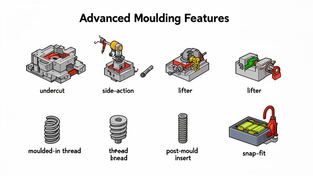
Solving for Undercuts with Side-Actions and Lifters
An undercut is any feature that prevents a part from ejecting cleanly from a mould cavity, such as snap-fit latches, side holes for connectors, or O-ring grooves. To produce these features, the tool requires moving components that form the feature and then retract before part ejection.
The two primary mechanisms are side-actions (also called slides or cams) and lifters.
- Side-Actions: These are moving blocks within the mould that travel perpendicular to the primary opening direction. They are robust, precise, and ideal for larger or critical external undercuts. The tradeoff is a significant increase in tool cost, complexity, and size.
- Lifters: These mechanisms are built into the mould base and move at an angle during mould opening, simultaneously lifting the part and retracting to release an internal undercut. Lifters are effective for features inaccessible to a side-action but are more delicate and may leave witness marks on the part surface.
The choice is an engineering tradeoff. For an external latch on a battery enclosure, a side-action is typically the more durable and reliable solution. For an internal clip inside a compact housing, a lifter may be the only viable option.
Tradeoff Analysis: A tool with side-actions can easily cost 15-30% more than a simple open-and-shut tool. This upfront investment must be weighed against the value of the integrated feature versus the cost and complexity of a secondary assembly operation. For high-volume production, the efficiency of moulding the feature in-situ usually prevails.
Handling Threads: Moulded-In vs. Post-Mould Inserts
When a design requires threads for assembly, you face a critical decision: mould the threads directly into the plastic or use post-moulded metal inserts.
Moulding threads directly appears cheaper by eliminating a component and assembly step. However, it requires a complex and costly unscrewing mechanism in the mould or a split-line thread design that can compromise strength. Furthermore, plastic threads lack the durability for applications requiring frequent assembly and disassembly.
For robust, high-strength connections, threaded inserts are almost always the superior choice. Typically installed via heat-staking or ultrasonic welding after moulding, this approach adds an assembly step but provides a durable metal thread capable of handling repeated use and higher torque values.
Real-World Scenario: Designing an AMR Battery Enclosure
Consider a ruggedized battery enclosure for an autonomous mobile robot (AMR) operating in a demanding warehouse environment. The product requirements dictate several advanced features:
- Robust Snap-Fit Latches: To secure the lid, creating undercuts.
- Threaded Mounting Points: For fastening the enclosure to the robot chassis, demanding strong metal threads.
- Sealing Groove: An O-ring groove for ingress protection, which is also an undercut.
In this scenario, side-actions are the optimal solution for the snap-fit latches and O-ring groove, providing the precision needed for a reliable seal and secure closure. For the mounting points, heat-staked threaded inserts are specified to ensure the enclosure remains securely fastened despite constant vibration.
This decision-making process is guided by a holistic view of the product's operational life. As injection molding market trends and projections show, the industry's growth is driven by the production of more intricate and high-tolerance components. By making these DFM decisions early, the engineering team accepts a higher initial tooling cost as a calculated investment to meet core functional and reliability requirements, thereby preventing far more costly field failures and warranty claims.
De-Risking Your Design with Simulation and Prototyping
A CAD model is a hypothesis; a manufacturable part is a proven outcome. The validation phase bridges this gap, providing a crucial reality check for your design. Skipping this stage on a complex part is a significant, unmitigated program risk.
The objective is to identify and resolve potential manufacturing issues before cutting steel for the production tool. Each problem caught via simulation or prototyping prevents an expensive and time-consuming tool modification. High-performing teams treat verification not as a final gate, but as an iterative process that systematically retires risk and builds confidence.
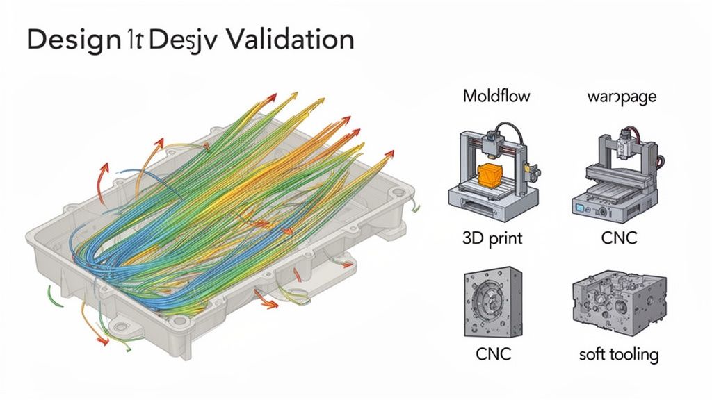
Predict Manufacturing Outcomes with Moldflow Analysis
Before fabricating any physical parts, a simulation should be conducted. Moldflow analysis is a simulation tool that predicts how molten plastic will flow into, fill, and cool within the mould cavity. For any part with complex geometry, tight tolerances, or cosmetic requirements, this analysis is not optional—it is essential.
Moldflow provides early visibility into critical manufacturing defects:
- Fill Pattern: Verifies complete filling of the cavity, preventing "short shots."
- Weld Lines: Identifies where melt fronts converge, allowing their placement to be moved away from structurally or cosmetically critical areas.
- Air Traps: Pinpoints locations where air may be trapped, informing the placement of vents in the tool.
- Warpage and Shrinkage: Predicts how the part will deform upon cooling, enabling design or process adjustments to compensate.
A Moldflow analysis performed before tool kickoff is one of the highest-leverage risk reduction activities available. The insights can prevent months of schedule delay and tooling rework costs that can easily exceed $50,000 on a complex mould.
Applying Practical Tolerancing with GD&T
Once mouldability is confirmed, you must define precision. This is the role of Geometric Dimensioning and Tolerancing (GD&T). A common failure mode is over-tolerancing—applying unnecessarily tight tolerances to all dimensions. This practice significantly drives up the cost and complexity of tooling, quality control, and manufacturing.
Instead, identify the critical-to-function (CTF) dimensions. These are the few features essential for proper assembly and performance. Apply tight tolerances only to these features. For all other non-critical dimensions, specify tolerances that are achievable with a standard injection moulding process (typically ±0.1mm or 0.005 inches). This pragmatic approach controls costs without compromising function.
A Phased Prototyping Strategy
Simulation provides data, but physical prototypes provide tangible feedback. Your prototyping strategy should evolve to retire specific risks at each stage of development. A well-defined prototype to product strategy is essential for navigating this path efficiently.
Early Stage: Form and Fit Validation
- Goal: Quickly assess ergonomics, aesthetics, and basic assembly.
- Method: 3D Printing (FDM/SLA). Provides parts quickly and inexpensively.
- Risk Retired: Confirms basic geometry, clearances, and user interface feel.
- Constraint: Material properties are not representative of the final part; not suitable for functional or thermal testing.
Mid Stage: Functional Testing with Production-Intent Materials
- Goal: Test mechanical performance using a material with similar properties to the final plastic.
- Method: CNC Machining. Creates a highly accurate part from a solid block of the chosen plastic or a close equivalent.
- Risk Retired: Validates structural integrity and performance under expected loads.
- Constraint: Cannot replicate moulding-specific artifacts like weld lines or internal stresses. Slower and more expensive than 3D printing.
Late Stage: Pre-Production Verification
- Goal: Produce a small batch of parts that are as close to production as possible for final validation.
- Method: Soft Tooling (Aluminum Molds). An aluminum tool can produce several hundred to a few thousand parts using the final production-grade plastic.
- Risk Retired: Validates the final part design, material selection, and moulding process parameters before committing to expensive steel tooling.
- Constraint: While cheaper than steel, an aluminum tool is still a significant investment and has a limited operational life.
By layering these techniques—simulation, practical tolerancing, and a phased prototyping plan—you systematically eliminate uncertainty and de-risk the substantial financial and schedule commitment of production tooling.
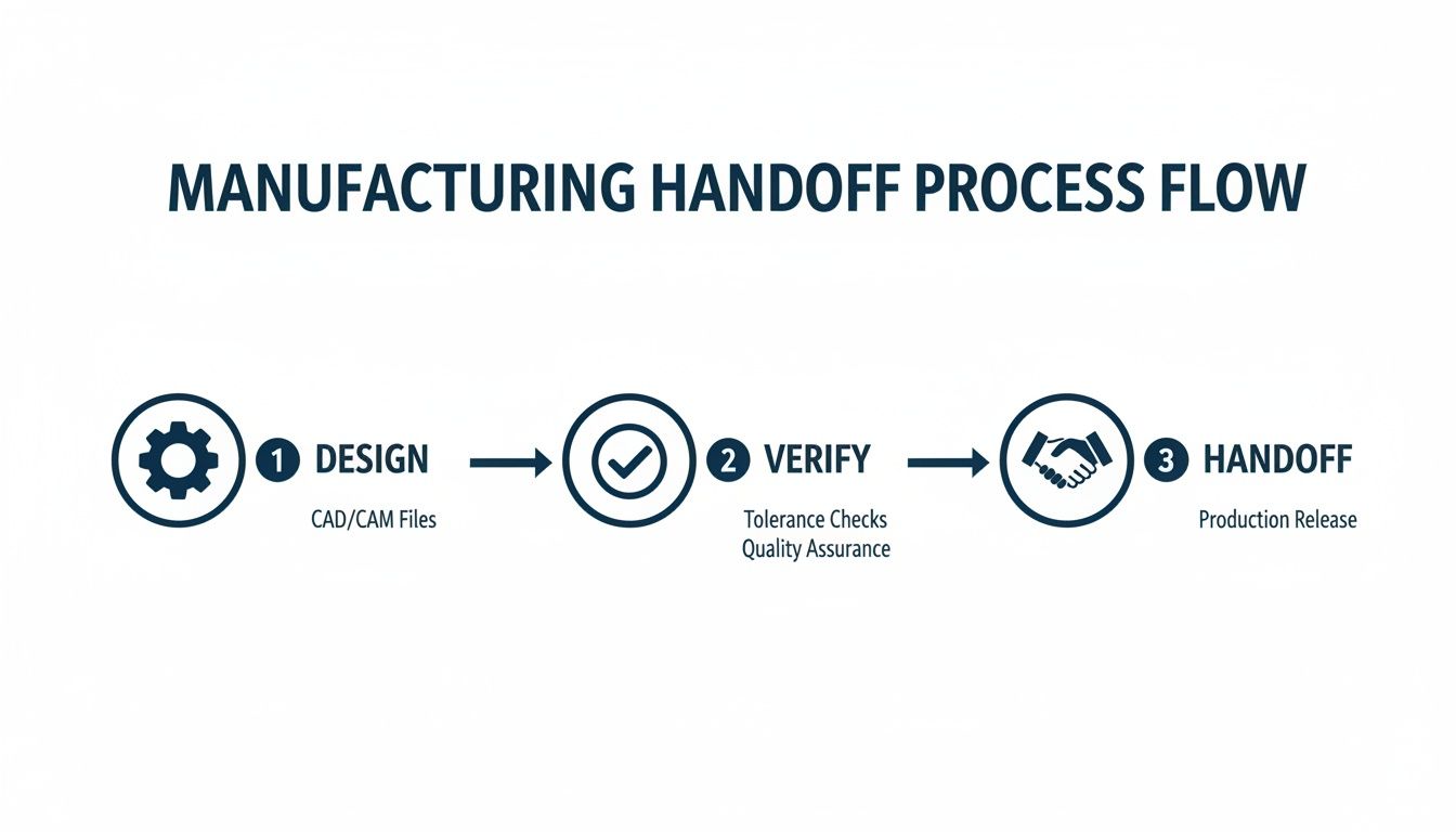
Ensuring a Seamless Manufacturing Handoff
A well-designed part can still fail due to a poor handoff to manufacturing. The transition from design to the contract manufacturer (CM) is a common point of failure, where miscommunication and incomplete information lead directly to delays, budget overruns, and tool rework.
A weak handoff creates ambiguity, forcing the moulding partner to make assumptions about design intent. This is how T1 samples arrive that bear little resemblance to the intended design, triggering costly and time-consuming revision cycles.
The solution is to treat the handoff as a critical project deliverable by creating a comprehensive and unambiguous Technical Data Package (TDP). This package serves as the single source of truth, leaving no room for interpretation.
Building Your Technical Data Package
A robust TDP is more than just a 3D model. It is a curated set of documents that enables your CM to build, inspect, and validate your part using only the information provided.
Your TDP must include these core elements:
- Fully Annotated 3D CAD Model: The master file for toolpath generation, provided in a universal format like STEP. It must include final geometry, draft angles, fillets, and ribs.
- Detailed 2D Drawings: These communicate precision. Use them to specify all CTF dimensions, GD&T for key features, overall part tolerances, and quality standards.
- Material and Color Specifications: Be explicit. Specify the exact material grade (e.g., "Sabic Lexan 940"), colorant code (e.g., Pantone 485 C), and any required additives (e.g., UV inhibitors, flame retardants per UL94).
- Surface Finish Requirements: Use a standardized system like SPI (Society of the Plastics Industry) or Mold-Tech to define the required texture or polish for every surface, eliminating subjectivity.
A complete TDP shifts the operational dialogue from "What was the intent here?" to "Did the part meet the specification?" This professionalizes the engagement and establishes an objective standard for acceptance.
Defining Quality Upfront
Your handoff must clearly define the criteria for success. Vague quality standards are a recipe for conflict. Provide a detailed inspection plan before tool manufacturing begins.
This plan should specify measurement methods (e.g., calipers, CMM, go/no-go gauges) for each critical dimension and define the Acceptable Quality Limit (AQL). For cosmetic parts, include boundary samples—physical examples of the best- and worst-case acceptable appearance—to remove subjectivity from inspection. This early alignment on quality is a cornerstone of effective design for testability and manufacturability, forcing a critical conversation about process capabilities before production starts.
The T1 Sample Review and Beyond
The T1 sample review is the first physical validation of your TDP. These first parts off the production tool require meticulous inspection against your 2D drawing and quality plan. A detailed inspection report documenting every deviation becomes the objective basis for any required tooling adjustments. As the latest industry analysis shows, increasing automation in moulding is driving higher precision, making the T1 review process more efficient and data-driven.
Use this checklist to ensure your handoff is airtight and enables a smooth transition from design file to finished part.
Manufacturing Handoff Checklist for Injection Moulded Parts
| Deliverable/Topic | Key Details to Include | Reason for Importance |
|---|---|---|
| 3D CAD Model | Final geometry, native & STEP files, draft, fillets | Defines the part's shape and serves as the master for toolpath generation. |
| 2D Drawings | Critical dimensions, GD&T, material/color specs, finish callouts | Communicates tolerances and quality standards that the model alone cannot convey. |
| Quality & Inspection Plan | Measurement methods, AQL, critical inspection points, boundary samples | Removes subjectivity from the acceptance process and aligns on "what good looks like." |
| Packing & Shipping | Packaging requirements, labeling, shipping methods | Prevents damage to parts during transit and ensures proper handling and identification. |
Following this checklist doesn't just simplify your CM's job; it protects your project by minimizing risk, accelerating your timeline, and professionalizing the critical transition from design to mass production.
Putting DFM to Work in Your Organization
The next step is to embed these Design for Injection Moulding principles into your team's operational workflow. This transforms theory into tangible results: lower tooling costs, faster cycle times, and higher-quality parts. The goal is to make design for injection moulding an early-stage, reflexive habit, not a late-stage gatekeeper. Waiting until a CAD model is "finalized" to consider manufacturability guarantees rework, schedule slips, and frustrated engineers.
High-performing teams integrate DFM from the earliest architectural discussions, treating manufacturability as a primary design constraint. This proactive approach is fundamental to shipping complex products on time and on budget.
From Theory to Practice: Your Next Steps
You don't need a massive organizational overhaul to start seeing benefits. Real change begins with targeted, high-impact actions.
Here are three concrete steps to take this week:
- Schedule a Cross-Functional Design Review. Convene mechanical, electrical, and systems engineers with a program manager. Use the principles in this guide as the agenda. Systematically challenge assumptions about wall thickness, draft, and features that imply complex tooling. The explicit goal is to identify and resolve DFM issues before design freeze.
- Establish a Standard DFM Checklist. Codify this guide's key takeaways into a one-page checklist. Cover the non-negotiables: uniform wall thickness, draft, rib/boss rules, and material selection criteria. Make this checklist a required artifact for every mechanical design review.
- Engage Manufacturing Partners Early. Select two or three potential moulding partners and schedule preliminary design reviews, even if you are months away from tool kickoff. Their feedback on early-stage concepts is invaluable and can prevent tens of thousands of dollars in downstream tool modifications.
Embedding DFM into Your Team’s DNA
Ultimately, successful DFM implementation is about changing organizational habits. It requires fostering a culture where manufacturability is considered as fundamental as functional performance.
The most effective teams don't treat DFM as a tax on the design process. They treat it as a core competency. They understand that designing for the manufacturing process is an integral part of designing the product itself.
This cultural shift begins when leadership celebrates good DFM practices. When a design review identifies a potential moulding issue early, recognize it as a team win. Quantify the impact—"Catching that deep, thick rib likely saved us three weeks of tool rework and $8,000 in steel-safe modifications"—to draw a clear line between an engineering decision and a business outcome.
Integrating these practices across your entire product development lifecycle is key. For a broader framework, see our guide on Design for Manufacture and Assembly (DFMA). By providing your team with the right tools and fostering a proactive mindset, you transform DFM from a reactive cleanup chore into a powerful strategic advantage.
If your team is struggling to bridge the gap between a validated prototype and a production-ready design, an independent review can identify critical risks before they impact your schedule and budget.