
Table of Contents
What Is Embedded Systems Engineering? Embedded systems engineering is the discipline of creating dedicated computing systems by integrating hardware, firmware, and software. It’s the critical capability behind intelligent products—from life-saving medical devices and industrial robots to smart home gadgets—where computational power must perform flawlessly within strict physical, power, and cost constraints.
Failing to integrate hardware, firmware, and software from day one is the single biggest reason complex product launches fail. When these disciplines operate in silos, the outcome is predictable: costly last-minute integration nightmares, blown market windows, and unreliable products that fail in the field. This isn’t just a technical problem; it’s a business disaster leading to budget overruns, a damaged brand, and the operational headache of managing returns and warranty claims.
This guide is a pragmatic framework for the VPs of Engineering, CTOs, and Program Managers responsible for delivering complex products on time and on budget. It’s not for hobbyists or students seeking academic definitions. The core recommendation is this: successful embedded product development depends on a unified, systems-level approach that bakes in verification, validation, and manufacturability from the start.
In this guide, you will learn:
- How to break down the three pillars—hardware, firmware, and software—and manage their hidden dependencies to prevent project blow-ups.
- How to structure teams and workflows to tear down silos, foster collaboration, and eliminate the friction that causes integration failures.
- How a relentless focus on Design for Testability (DFT) and Manufacturability (DFM) directly translates to higher quality, lower costs, and a faster path to market.
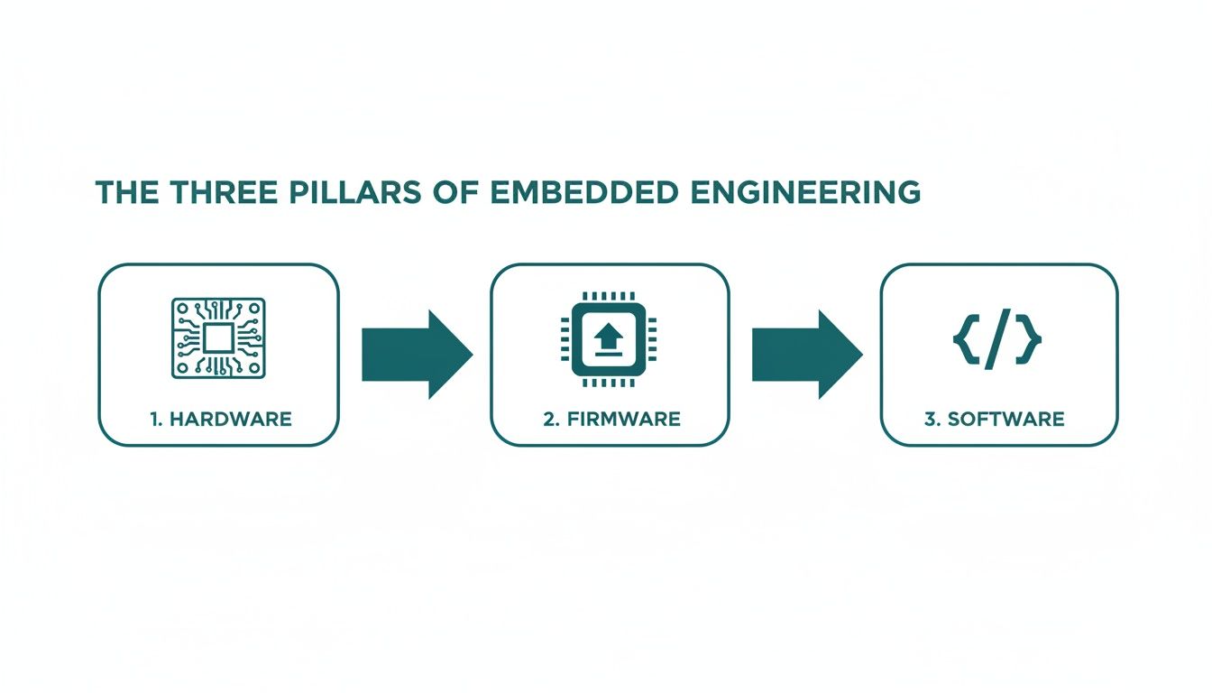
The Three Pillars of Embedded Engineering
Every successful embedded system is built on three pillars: Hardware, Firmware, and Software. In high-performing teams, these are not separate departments that toss work over the wall but deeply integrated disciplines. The most expensive, schedule-killing failures almost always happen at the handoffs between these groups. Imagine a software team designing a feature unaware that the hardware’s power budget can’t support it, or a hardware team laying out a board without understanding the bootloader sequence, making it impossible to reliably program in a factory setting.
These aren’t hypothetical scenarios; they happen constantly. This is why a single-threaded ownership model—where one leader is accountable for the entire system from silicon to screen—is so powerful. It forces integration risks into the open early, long before they can derail a project during a frantic, last-minute debug session.
Hardware: The Physical Foundation
Hardware is the tangible system: the printed circuit board (PCB), microcontroller, sensors, power supply, and connectors. However, great hardware engineering extends beyond component selection. Success is defined by how well the design anticipates the real-world demands of manufacturing, testing, and field reliability. This is where Design for Manufacturability (DFM) and Design for Testability (DFT) are non-negotiable.
- DFM ensures the product can be built reliably and cost-effectively at scale. It involves decisions like component placement to optimize the soldering process or panel layout to maximize manufacturing yield.
- DFT is the practice of embedding diagnostics into the board itself, such as adding test points, JTAG/SWD access, and other features that enable rapid fault diagnosis on the production line.
Ignoring these disciplines creates significant downstream costs. A board that is difficult to assemble will suffer from low manufacturing yield, driving up the per-unit cost. A board without adequate test points becomes a black box on the factory floor, making failure analysis time-consuming and expensive.
Firmware: The Bridge Between Hardware and Software
If hardware is the body, firmware is the nervous system. It is specialized code residing directly on the hardware, typically in non-volatile memory. As the first code to execute on power-up, it is responsible for initializing the hardware and providing a stable platform for higher-level software.
Firmware is where the digital world of software meets the analog reality of physics. It’s the critical layer responsible for handling real-time constraints, managing peripherals, and ensuring the system can boot reliably every single time.
This layer contains some of the most critical code in the system:
- Bootloaders: Minimalist programs that initialize the processor and memory before launching the main operating system or application.
- Device Drivers: Essential code enabling the OS to communicate with specific hardware components like a radio chip, an accelerometer, or a memory controller.
- Real-Time Operating Systems (RTOS): Specialized operating systems designed to manage tasks with deterministic timing. An RTOS is essential for any system where missing a deadline could have catastrophic consequences, such as in medical devices or industrial controls.
Firmware development requires a deep understanding of both hardware datasheets and software principles. A classic failure mode is a timing bug where a software command is issued before the hardware is physically ready, leading to intermittent and difficult-to-diagnose system failures.
Embedded Software: The Application and User Experience
The embedded software is the application layer that delivers the product’s features and user experience. It builds upon the foundation laid by the hardware and firmware, whether it’s the graphical interface on a medical monitor, the control logic in a factory robot, or the networking stack in an IoT device.
Application-level decisions have a significant impact on the entire system. An inefficient algorithm can consume excessive processing power, forcing the use of a more expensive microcontroller and increasing the unit cost. A power-hungry feature can drain the battery, undermining the product’s core value proposition. This is where systems thinking is paramount. The software team must understand and operate within the constraints of the hardware. The handoffs between these disciplines are where projects succeed or fail.
| Discipline | Key Responsibilities | Key Deliverables | Common Failure Modes to Mitigate |
|---|---|---|---|
| Hardware | Component selection, schematic capture, PCB layout, power management, signal integrity, DFM/DFT. | Schematics, PCB layout files (Gerbers), Bill of Materials (BOM). | Component obsolescence, poor signal integrity causing data corruption, insufficient test points, designs that are costly to manufacture. |
| Firmware | Bootloaders, board bring-up, device drivers, peripheral configuration (I2C, SPI), RTOS integration. | Bootloader binaries, device drivers, Board Support Package (BSP). | Race conditions, hardware/software timing violations, incorrect peripheral configuration, memory corruption. |
| Software | Application logic, UI/UX implementation, networking stacks, data management, system security. | Application code, UI assets, communication protocols, final executable image. | Inefficient algorithms draining CPU/battery, memory leaks, poor user experience, ignoring hardware resource limitations. |
Navigating The Embedded Product Development Lifecycle
Bringing an embedded product from concept to mass production is a disciplined, iterative process. A common failure pattern is the siloed, linear approach: hardware designs a board, throws it over the wall to firmware, who then hands it off to software. This methodology is a recipe for disaster, frequently leading to catastrophic integration problems late in the development cycle that force costly redesigns and schedule delays.
A successful embedded product lifecycle is iterative and collaborative, focused on creating tight feedback loops to systematically eliminate risk at every stage. The best teams understand that a small architectural decision can have massive ripple effects on manufacturing yield and long-term field reliability. This process isn’t a sequence of handoffs but a parallel management of interconnected disciplines. The discipline is what allows companies to capitalize on a market projected to grow from USD 106.5 billion in 2026 to USD 173.9 billion by 2035, a trend fueled by the explosion of smart devices. You can explore more insights about the embedded systems market growth projections.
Phase 1: Requirements and Architecture
This is where a project is made or broken. Before any engineer considers a component, the “what” and “why” of the product must be defined with absolute clarity. The key output is the System Requirements Document (SRD), which captures functional needs, performance targets, environmental constraints, and regulatory hurdles. Rushing this stage is a false economy. The SRD is the contract between stakeholders that prevents scope creep and aligns the team. This phase is also where foundational tradeoffs are made, such as selecting a microcontroller with sufficient performance for future features or choosing a wireless module that balances power consumption and regulatory compliance.
Phase 2: Prototyping and Bring-Up (EVT)
With a solid architecture, the focus shifts to bringing the first hardware to life. This stage answers one question: “Does this design work?” The climax is the Engineering Validation Test (EVT) build. EVT units are typically the first boards assembled by a contract manufacturer. Their purpose is not to be shippable products but to validate the core design through board bring-up: a methodical process of powering up the board, verifying power rails, checking clock signals, and confirming the firmware can boot the processor. This is an intense period of hands-on debugging where hardware and firmware engineers collaborate to resolve inevitable issues.
Phase 3: Verification and Validation (V&V)
Once the core design is proven during EVT, the project enters the Verification and Validation (V&V) phase. The objective is to rigorously test the design against every requirement in the SRD. This goes far beyond basic functional checks.
- Verification asks: “Did we build the product right?” It involves a comprehensive suite of electrical, mechanical, and functional tests to confirm the design meets its specifications.
- Validation asks: “Did we build the right product?” It confirms the device meets end-user needs and performs correctly in its intended real-world environment.
A critical tool in this phase is Hardware-in-the-Loop (HIL) testing. HIL systems use specialized equipment to simulate real-world signals and environmental conditions, enabling automated, repeatable testing that would be impossible to perform manually. This is essential for identifying edge-case bugs and ensuring system robustness.
Phase 4: Manufacturing Ramp (DVT/PVT)
This is the transition from engineering prototypes to mass production, managed through two critical gates: Design Validation Test (DVT) and Production Validation Test (PVT). DVT builds use final, production-intent tooling to validate that the design can be manufactured reliably at scale, where early DFM and DFT planning pays dividends. PVT is the final dress rehearsal: the first official run on the actual manufacturing line, validating factory processes, quality control systems, and test fixtures.
A comprehensive manufacturing test plan is non-negotiable. It defines exactly how every single unit coming off the assembly line will be programmed, calibrated, and functionally tested. Without it, you are flying blind, unable to separate good units from bad and practically guaranteeing a flood of field failures.
Successfully clearing these gates requires meticulous planning and a strong partnership with your contract manufacturer, ensuring the design is optimized for their assembly lines and test capabilities.
Solving Challenges in High-Reliability Systems
While all embedded systems require discipline, products for regulated industries or harsh environments demand a higher level of engineering rigor. When a failure could lead to injury, major financial loss, or mission failure—as in medical devices, aerospace systems, and industrial automation—”good enough” is unacceptable. The design principles are stricter, testing is more exhaustive, and component choices are more conservative.
These high-reliability systems operate under severe constraints that must be architected in from day one. Safety and reliability cannot be added as features late in the development cycle; they must be part of the system’s DNA, influencing every decision from microcontroller selection to software structure.
Real-Time Constraints and System Safety
The defining characteristic of many high-reliability systems is the need to operate in real-time. This means the system must not only produce the correct result but do so within a predictable, guaranteed timeframe. In these systems, a late answer is a wrong answer.
A Real-Time Operating System (RTOS) is essential for managing these constraints. Unlike a general-purpose OS, an RTOS provides scheduling guarantees that allow engineers to prioritize critical tasks and ensure they always meet their deadlines. For example, in a medical infusion pump, the software task controlling the motor’s speed must execute precisely on schedule, without being delayed by a less critical task like refreshing the display. An RTOS provides the framework to enforce this hierarchy, which is fundamental to patient safety.
Non-Negotiable Reliability Patterns
To build systems that can be trusted with lives, engineers rely on proven reliability patterns designed to contain faults and ensure predictable behavior, even in failure scenarios.
- Watchdog Timers: A hardware timer that acts as a fail-safe. The main application must periodically reset the timer. If the software freezes or enters an infinite loop, it fails to reset the timer, which then expires and forces a system reset, returning the device to a known-good state.
- Brownout Detection (BOD): A hardware circuit that monitors the system’s supply voltage. If the voltage drops below a safe operating threshold, the BOD circuitry holds the microcontroller in a reset state, preventing erratic behavior or memory corruption due to insufficient power.
- Fault Containment: An architectural strategy to isolate software components, often using a memory protection unit (MPU). If one component crashes, the MPU acts as a firewall, preventing it from corrupting the memory of other critical components and containing the failure.
Furthermore, integrating robust security in the software development life cycle is non-negotiable for protecting sensitive data and ensuring system integrity.
Use Case: Medical Infusion Pump
Consider a hospital infusion pump, a device that must deliver medication with precision under strict regulatory oversight (e.g., FDA), requiring compliance with standards like ISO 13485 (medical device quality) and IEC 62304 (software lifecycle).
In a device like an infusion pump, every design choice must be traceable back to a specific safety requirement. The architecture isn’t just about making the pump work; it’s about proving it cannot fail dangerously.
The engineering team must design for safe failure states. If a sensor fails, the system cannot continue pumping. It must halt, trigger an audible alarm, and display a clear error message. This “fail-safe” behavior must be intentionally designed and rigorously tested. This process demands meticulous documentation, formal code reviews, and a verification plan that maps every test case back to a specific system requirement.
Essential Engineering Skills, Tools, and Deliverables
Shipping a successful embedded product requires discipline, process, and the understanding that the work extends beyond the compiler. For technical leaders, de-risking a project and achieving predictable results depends on ensuring the team has the right skills, tools, and documentation.
While expertise in C/C++ is foundational, the most effective engineers possess strong systems-thinking skills. They don’t just see lines of code; they see the entire system, understanding how a firmware change might affect electrical characteristics or how a software choice could impact manufacturing yields. This perspective is what separates teams who ship robust products from those trapped in an endless debug cycle.
The Modern Engineer’s Skillset
Beyond coding, engineers who drive success have mastered several key disciplines:
- Hands-On Hardware Debugging: Proficiency with an oscilloscope, logic analyzer, and multimeter is non-negotiable for probing a PCB and diagnosing issues with signals and power rails.
- Mastery of Version Control: A deep understanding of Git for managing complex codebases, especially with multiple developers, is essential for maintaining sanity and traceability.
- Operating System Fundamentals: A solid grasp of OS concepts is vital, particularly as Embedded Linux gains prominence. The Linux embedded systems market was valued at USD 0.48 billion in 2025 and is expected to nearly double to USD 0.90 billion by 2035, with 46% of IoT and embedded developers already using it. Discover more insights about the Linux embedded systems market.
The Essential Toolchain Beyond the IDE
A developer’s code editor is just one piece of the puzzle. A mature engineering organization invests in a broader toolchain that enables robust, repeatable development. This includes a continuous integration (CI) pipeline tailored for hardware, which can automatically build firmware, run static analysis, and execute unit tests on every code check-in. This automation catches bugs early, long before they reach physical hardware, saving significant time and cost.
The most mature engineering teams treat their project documentation with the same rigor as their code. Deliverables like a verification plan or a risk register are not bureaucratic overhead; they are essential risk-mitigation tools that provide critical program visibility.
Critical Deliverables for Program Success
The paper trail of an engineering project is tangible proof of its discipline. These artifacts ensure that decisions are recorded, requirements are met, and everyone is aligned. Consistently producing these deliverables is a hallmark of high-performing teams.
| Development Phase | Critical Deliverable | Business Impact of This Deliverable |
|---|---|---|
| Requirements & Planning | Risk Register | A living document that identifies and tracks technical, schedule, and manufacturing risks, assigning probabilities and mitigation plans. It turns "what if" into "here's how we'll handle it." |
| Architecture & Design | Architecture Design Document (ADD) | Details the high-level structure, interfaces, and design choices. Prevents siloed development and ensures the system is cohesive and scalable. |
| Implementation & Test | Verification & Validation (V&V) Plan | Explicitly maps every system requirement to a specific test case. Guarantees 100% test coverage and proves the product does what it’s supposed to do. |
| Post-Baseline | Engineering Change Order (ECO) Process | A formal process for managing all changes after a design is "frozen." This prevents uncontrolled chaos that introduces new bugs and disrupts manufacturing. |
For leaders, demanding these deliverables provides a concrete checklist to assess project health and enforce engineering discipline, connecting technical activities directly to business outcomes. If you’re looking to implement these best practices, our experts in embedded firmware development services can provide the guidance to build a more predictable engineering process.
Deciding When to Partner with an Embedded Engineering Expert
The decision to engage external engineering expertise versus building the capability in-house is a high-stakes choice for any technical leader. The right partner can rescue a stalled program or accelerate time-to-market. The wrong one adds friction and drains the budget. Engaging a partner isn’t a sign of weakness; it’s a strategic move to manage risk and inject specialized skills precisely when needed.
Clear Signals You Need External Expertise
Three common scenarios should make an expert partner a primary consideration:
- Your team is software-heavy: Many companies have exceptional talent in cloud and mobile development but lack the specialized firmware and hardware skills for a physical product. An expert partner bridges this gap, helping avoid common pitfalls in hardware bring-up, power management, and driver development.
- A critical project is stalled or failing: When a key program is losing time and money to technical roadblocks, a fresh perspective is invaluable. A technical rescue mission, led by engineers who have solved similar problems, can perform a rapid root-cause analysis and stabilize the design.
- You need to accelerate time-to-market: Speed is a critical competitive advantage. An on-demand engineering team allows you to scale capabilities instantly, bypassing the lengthy hiring process to hit aggressive launch targets.
A unified delivery model is absolutely critical here. The goal is to find a partner who reduces handoffs, not one who creates more. An integrated team that maintains technical continuity from the first prototype all the way to production is the key to de-risking the entire program.
A Use Case in Industrial Automation
Consider an industrial automation company needing to modernize a legacy controller. Their in-house team excels at PLC logic but has no experience with modern microcontrollers or wireless connectivity. By engaging a full-stack partner, they gained a single point of accountability for the entire hardware, firmware, and software integration. The partner architected a new system, designed a manufacturable PCB, and developed robust firmware. This integrated approach ensured the final design was optimized for performance, manufacturing, and long-term support. This is increasingly important as specialized hardware like embedded FPGAs become more common, a market expected to hit USD 596.11 million by 2035. Learn more about the rapid growth in eFPGA IP.
Our guide to choosing the right embedded systems consulting partner offers a framework for evaluating your options.
Frequently Asked Questions About Embedded Systems Engineering
Here are answers to common questions from technical leaders embarking on a new embedded project, from the perspective of a team that sees products through from design to the factory floor.
What Are the Biggest Risks in an Embedded Systems Project?
The greatest risks in any embedded project almost always hide at the interfaces—the handoff points between disciplines where unspoken assumptions and reality collide. The most dangerous blind spots appear in two places:
- Between hardware and firmware: A classic failure mode where the firmware team discovers a critical hardware limitation on the first prototype that was missed on paper, forcing a costly board respin and delaying the project.
- Between engineering and manufacturing: This occurs when a design is finalized without addressing how it will be built and tested at scale, leading to production issues, low yields, and high per-unit costs.
The only way to mitigate these risks is through integrated teams, a robust verification plan, and meticulous documentation like an Architecture Design Document. High-performing teams force these tough conversations to happen before a design is frozen.
How Is Embedded Software Different from Application Software?
The single defining difference is constraints. An application developer for a PC or smartphone operates in a world of abundant memory and processing power. An embedded engineer operates within strict, non-negotiable limits.
Embedded software is defined by its direct interaction with the physical world, where resource constraints are severe, timing is often non-negotiable, and the consequences of failure can be catastrophic.
Consider these differences:
- Resource Limitations: Embedded systems have finite, often minimal, memory, CPU cycles, and power. Every line of code must be efficient.
- Real-Time Requirements: In many systems, a task finishing late is as bad as producing the wrong result. Timing is a hard requirement.
- Direct Hardware Interaction: Embedded code directly manipulates hardware registers, manages peripherals, and responds to physical sensors.
- Severe Consequences of Failure: If a mobile app crashes, it’s an annoyance. If the firmware in a pacemaker or a car’s braking system fails, the outcome can be far more serious.
How Can We Ensure Our Embedded Product Is Manufacturable?
Ensuring manufacturability is not a final checklist item but a parallel track that must run from the project’s inception. A Design for Manufacturability (DFM) and Design for Testability (DFT) mindset must be integrated from the architectural phase. To avoid a production nightmare, these actions are non-negotiable:
- Engage Your Contract Manufacturer (CM) Early. Treat your CM as a design partner. Get their feedback on component choices and PCB layout to ensure your design aligns with their factory’s capabilities.
- Design for Testability (DFT). Your hardware design must include features for production line testing, such as accessible test points and programming headers, to enable rapid failure diagnosis.
- Create a Comprehensive Manufacturing Test Plan. This document is your recipe for quality, defining in detail how every unit will be programmed, calibrated, and functionally tested before leaving the factory.
At Sheridan Technologies, we specialize in de-risking complex product development by integrating design, verification, and manufacturing readiness from the start. If you’re facing integration challenges or need to accelerate your path to production, consider requesting a Manufacturing Readiness Assessment with our experts.