
Table of Contents
Design for Manufacturing (DFM) is the engineering discipline of designing products so they are easy to manufacture. This isn’t a final checklist item; it’s a strategic approach that integrates manufacturing process constraints directly into the design phase. Ignoring DFM means discovering fatal flaws on the factory floor instead of in a CAD file, leading to catastrophic budget overruns, schedule delays, and low production yields. The stakes are simple: get this right, and you gain a competitive advantage; get it wrong, and you risk the entire product launch.
This guide is for engineering leaders, program managers, and lead hardware engineers responsible for shipping complex, reliable products. It’s not for hobbyists or teams where cost and scale are afterthoughts. The core takeaway is that embedding DFM from the earliest architectural decisions is the most effective way to control cost, accelerate time-to-market, and reduce program risk.
By reading this guide, you will learn to:
- Connect core DFM principles directly to business outcomes like cost, quality, and risk.
- Apply actionable DFM checklists for both electronics (PCBA) and mechanical design.
- Implement a DFM-first culture that bridges the gap between design and production.
What is the business impact of ignoring DFM?
Getting a prototype to work is a critical milestone, but it’s a world away from producing thousands of units reliably and profitably. This gap between a single functional unit and a market-ready product is where countless hardware programs fail. When manufacturability is an afterthought, the consequences are predictable: costly redesigns, painful production delays, plummeting yields, and a fragile supply chain. For any company shipping hardware, these aren’t just risks; they’re existential threats.
The Growing Importance of DFM
The market data confirms that DFM is now an indispensable discipline. The global market for DFM solutions sits at USD 10.3 billion and is projected to reach USD 12.5 billion by 2033. North America leads with a USD 3.5 billion market size and a projected 7.5% compound annual growth rate. This growth reflects a market-wide recognition that designing for the factory from day one is the clearest path to cutting rework, shrinking timelines, and lowering the total cost of bringing a product to market. You can dig into these DFM market projections on strategicrevenueinsights.com.
DFM vs. DFMA: A Quick Clarification
You’ll often hear DFM mentioned with Design for Assembly (DFMA). They are two sides of the same coin:
- DFM (Design for Manufacturing) focuses on making individual parts simple and efficient to fabricate.
- DFMA (Design for Manufacture and Assembly) focuses on making the process of putting all those parts together as simple as possible.
High-performing teams don’t treat them separately; they consider both in parallel. We dive deeper into this relationship in our complete guide to Design for Manufacture and Assembly.
DFM isn’t a final checklist item; it’s a parallel engineering track that runs from concept to production. Treating it as an afterthought is the most common—and expensive—mistake a hardware team can make. It transforms manufacturing from a potential bottleneck into a competitive advantage.
Core DFM Principles and Their Business Impact
Connecting DFM principles to real-world business outcomes is what matters most. The following table breaks down the core tenets of DFM, outlining the technical goals and the tangible business impact of getting each one right. This provides a clear framework for seeing how engineering decisions translate directly into financial and operational success.
Core DFM Principles and Their Business Impact
| DFM Principle | Technical Goal | Business Impact |
|---|---|---|
| Process Simplification | Minimize the number and complexity of manufacturing operations required. | Reduces manufacturing cycle time, lowers labor costs, and decreases the potential for process-related errors. |
| Standardization | Use standard parts, materials, and processes wherever possible instead of custom solutions. | Lowers component costs, improves supply chain reliability, reduces inventory complexity, and shortens lead times. |
| Part Reduction | Design single, multi-functional components instead of multiple simpler parts. | Decreases assembly time and cost, reduces part count and inventory, and minimizes potential points of failure. |
| Material Selection | Choose materials that are cost-effective, readily available, and well-suited to the chosen manufacturing process. | Controls material costs, ensures supply chain stability, and improves product performance and reliability. |
| Design for Testability & Assembly | Ensure the design facilitates efficient testing, inspection, and assembly. | Reduces labor costs for assembly and quality control, improves final product quality, and accelerates time-to-market. |
| Tolerance Optimization | Specify the widest possible tolerances that still ensure proper function and fit. | Lowers fabrication costs (tighter tolerances are more expensive), increases manufacturing yield, and reduces scrap rates. |
Ultimately, these principles are not just abstract engineering guidelines. They are direct levers you can pull to influence cost, quality, and speed. By embedding these concepts into your design workflow, you move from simply creating a functional product to engineering a successful one.
What are the 5 pillars of an effective DFM strategy?
An effective Design for Manufacturing strategy is a systematic framework built on five interconnected pillars. This approach turns vague goals into an actionable plan, ensuring every design decision is weighed against its real-world impact on the factory floor. These pillars give designers, engineers, and manufacturing partners a common language to prevent late-stage crises. Finding a flaw in a CAD model takes hours to fix; finding it on the assembly line can cost millions and delay a launch by months.
This diagram shows the fundamental split in the design process, highlighting how a product idea has to be optimized for both prototyping and manufacturing, not just one or the other.
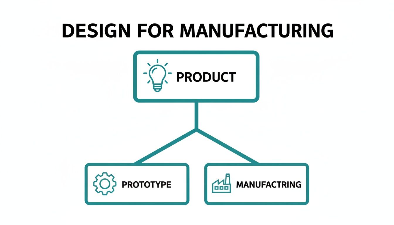
The visual drives home a core tenet of successful DFM: prototyping and manufacturing are parallel considerations you have to balance from day one, not sequential steps you get to later.
Pillar 1: Process Selection
Choosing the right manufacturing process is the most foundational decision, as it dictates subsequent choices on materials, geometry, and cost. The key is to match the design to the process—not force a process to accommodate an unsuitable design.
Common processes include:
- Injection Molding: Ideal for high-volume plastic parts but requires significant upfront tooling investment and designs with draft angles and uniform wall thickness.
- CNC Machining: Offers high precision across many materials but becomes expensive at volume, especially for complex geometries.
- PCB Assembly (PCBA): Governed by rules for component placement, soldering (reflow/wave), and inspection. DFM focuses on component spacing, panelization, and test point access.
- Sheet Metal Fabrication: Cost-effective for enclosures and brackets, but designs must respect bend radii and material properties to avoid cracking or warping.
Common Failure Mode: A classic mistake is designing a part with intricate undercuts for injection molding. This forces either impossibly complex tooling or a late-stage pivot to a less scalable process like multi-part machining, destroying the unit cost model.
Pillar 2: Design Simplification
Complexity is the enemy of manufacturability. Every extra part, feature, or operation introduces another opportunity for failure, cost, and delay. Design simplification is the relentless pursuit of efficiency. The primary goal is to reduce the total part count. A single, multi-functional component is cheaper to track, assemble, and manage than three separate parts. It also eliminates tolerance stack-up issues and simplifies the supply chain.
A design isn't finished when there is nothing left to add, but when there is nothing left to take away. This principle is the very heart of design simplification, directly connecting engineering elegance to business efficiency.
Pillar 3: Material Selection
Material choice directly impacts cost, performance, and process compatibility. An effective DFM strategy views materials through a manufacturing and supply chain lens.
Key questions to ask include:
- Cost and Availability: Is the material readily available from multiple suppliers, or is it a sole-sourced component with a long lead time? Supply chain risk is a massive factor.
- Process Compatibility: Does the material work well with the chosen manufacturing process? Some plastics are notoriously difficult to mold and result in low yields.
- Secondary Operations: Will the material require special finishing, coating, or heat treatment? These extra steps add cost and complexity.
Pillar 4: Standardization
Using standardized components is a powerful lever for controlling cost and risk. Every custom fastener, connector, or electronic component adds overhead for sourcing, qualification, and inventory management. Standardization means designing around common, off-the-shelf parts to leverage economies of scale and de-risk the supply chain. A standard M3 screw costs a fraction of a custom-machined one and is available from multiple distributors, protecting production from shortages.
Pillar 5: Realistic Tolerancing
Specifying tolerances is a delicate balancing act. Tolerances define the acceptable variation for a given dimension. While tight tolerances are necessary for critical interfaces, over-tolerancing is a common and expensive mistake. Tighter tolerances exponentially increase manufacturing costs by requiring more precise machinery, slower cycle times, and higher scrap rates. The DFM approach is to specify the loosest possible tolerance that still allows the part to function correctly. This requires a deep understanding of both product requirements and manufacturing process capabilities.
How DFM works in practice: An industrial sensor housing example
Theory is useful, but seeing DFM in action makes the value concrete. Let's walk through a real-world example of an industrial automation client who needed a ruggedized sensor housing. This scenario illustrates how a DFM review can transform a product’s cost structure and production timeline.
The Initial Design: A Recipe for High Costs and Risk
The client needed a durable, sealed enclosure for a new sensor module. Key constraints included a tight per-unit budget and a non-negotiable IP67 rating for dust and water protection. The initial design, drafted without DFM input, technically met requirements—on paper. It featured a complex aluminum body requiring multi-axis CNC machining to create internal mounting features and secure custom-cut gaskets.
This design raised immediate manufacturing red flags:
- High Per-Unit Cost: Multi-axis CNC machining is a slow, expensive process for volume production, far exceeding the client’s budget targets.
- Complex Assembly: The design required manual installation of a custom die-cut gasket, a classic point of failure where human error could easily compromise the critical IP67 seal.
- Supply Chain Risk: Relying on a specialized machining process narrowed the pool of qualified suppliers, creating a potential production bottleneck.
The DFM Review and Redesign
Our team initiated a DFM review with the contract manufacturer. The goal was to pivot the design to a more scalable and cost-effective process without compromising the IP67 rating or mechanical strength. A robust technical feasibility assessment is a crucial first step in any DFM process, as it ensures the new design can actually be manufactured efficiently.
The review led to a complete redesign centered on injection molding.
Key Design Iterations:
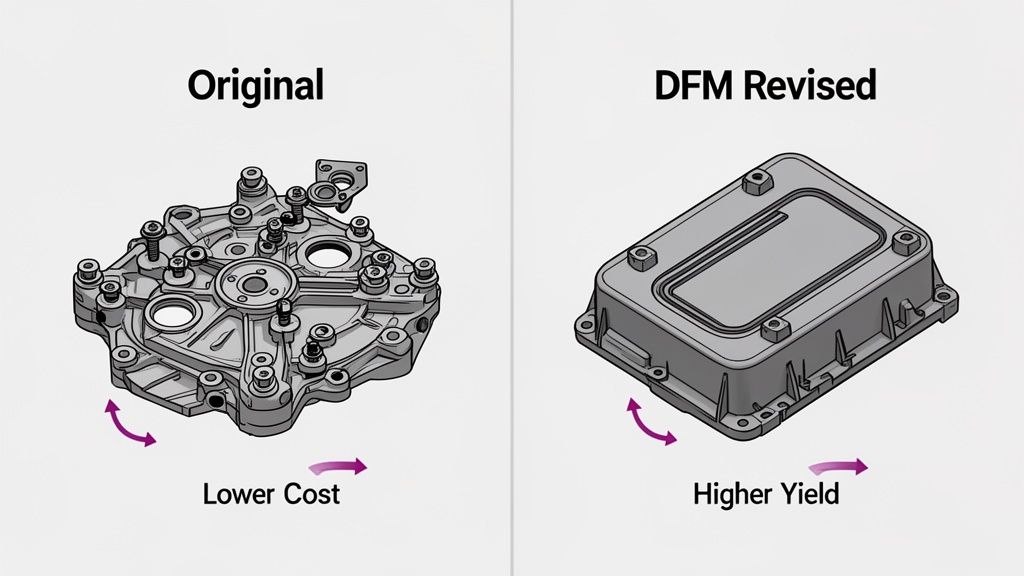
- Process Change: We switched from CNC machined aluminum to injection-molded, glass-filled polymer. This single change flipped the cost model from high per-unit costs to a higher one-time tooling investment with extremely low per-unit costs at scale.
- Geometry Simplification: We simplified the internal geometry, eliminating undercuts to allow for a much simpler—and cheaper—two-part mold. This is a classic DFM tradeoff: a minor internal layout change for a massive win in manufacturability.
- Seal Integration: The custom gasket was replaced with a groove molded directly into the housing, designed to accept a standard, off-the-shelf O-ring. This simplified assembly and made the seal far more reliable.
- Hardware Standardization: We replaced custom fasteners with standard stainless steel machine screws, cutting component costs and simplifying the supply chain.
The most impactful DFM decisions often involve changing the manufacturing process itself, not just tweaking the existing design. Moving from machining to molding fundamentally altered the product's entire cost and scalability equation.
The Business Outcome: A Clear Win
The results of the DFM-driven redesign were dramatic. They didn't just save a little money; they transformed the entire business case for the product. While this example focuses on a mechanical enclosure, the same principles are just as critical for electronics, which we cover in our guide to PCB Design for Manufacturing.
The new design delivered measurable improvements:
- Cost Reduction: A 40% reduction in the final per-unit production cost.
- Time-to-Market: The production ramp-up was accelerated by 6 weeks due to faster injection molding cycle times.
- Quality & Yield: The initial production run hit a 99.5% pass yield, driven by simplified assembly and a more reliable seal design.
This scenario is a powerful example of what design for manufacturing truly is: the strategic process that turns a functional prototype into a profitable, scalable product.
Actionable DFM checklists for design reviews
To bridge the gap between DFM principles and daily engineering work, use these high-impact checklists during design reviews. They are framed as simple questions with a "Why it Matters" note, connecting technical rules directly to business outcomes like cost, yield, or supply chain risk. The goal is to make DFM a reflexive part of your design process.
DFM Checklist for PCB Assembly
This checklist addresses common pitfalls in Printed Circuit Board Assembly (PCBA) that can cripple production schedules and inflate costs. A great PCB is not just electrically perfect; it is designed for automated assembly and test from the start.
| Checklist Item | Why It Matters (Business Impact) |
|---|---|
| Are critical components multi-sourced? | Reduces Supply Chain Risk: Sole-sourcing a critical IC creates a single point of failure. A shortage can halt production, delaying revenue and damaging customer trust. |
| Is the panelization strategy defined? | Controls Per-Unit Cost: Optimizing how many boards fit on a standard manufacturing panel directly impacts cost. Poor panelization wastes material and increases machine time. |
| Are fiducials placed correctly for automated assembly? | Improves Assembly Yield: Pick-and-place machines use fiducials for optical alignment. Incorrect placement leads to component misalignment, tombstoning, and increased rework and scrap. |
| Is there adequate clearance for AOI and test fixtures? | Enables Quality Control: Automated Optical Inspection (AOI) needs a clear line of sight. Insufficient clearance creates inspection blind spots, allowing defects to escape to the field. |
| Are thermal reliefs used on large copper planes? | Increases Soldering Reliability: Connecting pads directly to large copper planes acts as a heat sink, causing poor solder joints. Thermal reliefs ensure reliable connections and prevent field failures. |
| Are test points accessible and clearly labeled? | Reduces Debug Time: Inaccessible test points make troubleshooting during EVT/DVT and failure analysis on the production line slow and difficult, burning valuable engineering hours. |
DFM Checklist for Mechanical Enclosures
Mechanical enclosures have their own manufacturing rules. Breaking them leads to expensive tooling rework, poor part quality, and reliability issues. This is especially true for processes like injection molding, where upfront tooling costs are significant. For a deeper dive, check out our guide on design for injection moulding.
| Checklist Item | Why It Matters (Business Impact) |
|---|---|
| Is a consistent wall thickness maintained? | Prevents Cosmetic Defects & Improves Yield: Non-uniform walls in injection molded parts cause sink marks, warping, and inconsistent cooling, resulting in high scrap rates. |
| Are draft angles applied to all vertical faces? | Reduces Tooling Damage & Cycle Time: Draft angles allow the part to be ejected cleanly from the mold. Without them, parts can get stuck, damaging the expensive mold and slowing production. |
| Is the bend radius appropriate for the material and thickness? | Avoids Material Failure: In sheet metal, a bend radius that is too tight will cause cracking and structural weakness, leading to field failures. |
| Are holes and features spaced correctly relative to bends? | Prevents Part Distortion: Placing holes too close to a bend in sheet metal causes deformation during bending, leading to assembly problems and high scrap rates. |
| Have undercuts been minimized or eliminated? | Lowers Tooling Cost & Complexity: Undercuts in injection molding require complex, expensive tooling with side-actions. Designing them out significantly reduces tooling investment. |
These checklists aren’t just for a final review. The highest-performing teams use them during the design process, asking these questions at every stage from architecture to detailed CAD work. This proactive approach is the essence of building a DFM-first engineering culture.
How does DFM fit into modern digital manufacturing?
In high-performing teams, Design for Manufacturing is woven into the fabric of modern digital manufacturing. Its real power is unlocked when integrated with digital tools that bridge the gap between design and production. This strategic view transforms DFM from a reactive bottleneck into a proactive, continuous feedback loop. For CTOs and VPs of Engineering, this is a competitive advantage built on a robust digital thread—an unbroken line of data that flows from the initial sketch to the factory floor and back again.
The Digital Thread’s Role in DFM
The digital thread embeds DFM principles directly into engineering tools, providing foresight that was previously impossible.
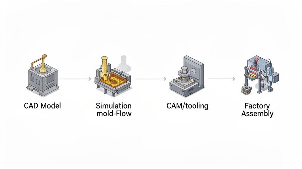
- CAD/CAM Integration: Modern CAD software often includes DFM analysis modules that flag issues in real-time, acting as a “spell-checker” for manufacturability.
- Advanced Simulation: Tools like mold-flow analysis for injection molding let engineers “manufacture” a product hundreds of times digitally before cutting steel, finding and fixing process-related risks early.
- Product Lifecycle Management (PLM): A PLM system acts as the single source of truth, ensuring that manufacturing engineers, quality teams, and suppliers all work from the same revision-controlled data.
This is a massive industry shift. The global digital manufacturing market is on track to hit USD 1,631.04 billion by 2034, growing at a 15.3% CAGR. The software solutions powering this, including design automation and simulation tools central to DFM, comprised over 45% of the market in 2024. This is a clear signal of where the industry is investing. You can explore more on the digital manufacturing market at market.us.
DFX: Integrating DFM with Sibling Disciplines
A mature approach recognizes that DFM is part of a family of “Design for X” (DFX) disciplines that must be balanced to minimize total program risk.
The core insight of top-tier engineering teams is that manufacturability, testability, and assembly are not sequential problems to be solved. They are intertwined aspects of a single, unified design challenge that must be addressed from the very beginning.
This integrated mindset brings DFM into close collaboration with its sibling disciplines:
- Design for Assembly (DFA): While DFM focuses on individual parts, DFA focuses on making the assembly process simple and error-proof. An effective DFM strategy is always informed by DFA.
- Design for Test (DFT): A product you can’t reliably test is a product you can’t reliably ship. DFT means designing in features like accessible test points or manufacturing firmware with diagnostic hooks to ensure every unit can be verified on the production line.
Bringing these disciplines together creates a powerful feedback loop where production test data (DFT) informs future design revisions (DFM), and simpler assembly (DFA) reduces manufacturing defects. This holistic view is how leading companies turn manufacturing from a late-stage hurdle into a core competitive strength.
How to build a DFM-first culture in your organization
Achieving DFM excellence is less about a specific tool and more about a fundamental cultural shift. A DFM-first culture treats manufacturability as a core design requirement from day one. This requires intentional leadership to break down the traditional walls between design and production, transforming how teams collaborate.
Ignoring the cultural component is the most common reason DFM initiatives fail. Without it, teams revert to old habits, tossing designs “over the wall” and hoping for the best, leading to late-stage rework, blown budgets, and delayed launches.
Fostering Early Collaboration
The first step is to dismantle silos. Design and manufacturing engineers must operate as a single, integrated team.
- Integrated Project Teams: From the concept phase, embed manufacturing engineers or key supplier representatives directly into the design team. Their early input on process limitations and cost drivers is invaluable.
- Joint Design Reviews: Make DFM a standing agenda item in all design reviews, not a separate, one-off gate. This forces a continuous conversation about production realities.
This early alignment prevents teams from investing weeks into a concept that is unbuildable or prohibitively expensive.
Establishing Clear Guardrails and Feedback Loops
Collaboration requires structure to be effective. Documented guidelines and data-driven feedback create a scalable and repeatable DFM process.
The goal of a DFM-first culture is to make manufacturing expertise ambient. It should be so deeply integrated into the process that designing for the factory floor becomes an instinct, not an exception.
To get there, engineering leaders must:
- Develop DFM Guidelines: Create and maintain a living document of DFM rules tailored to your most common manufacturing processes (e.g., injection molding, PCBA). This gives designers clear guardrails.
- Use DFM Software: Integrate automated DFM analysis tools into your CAD software. These tools act as a first line of defense, catching common errors in real-time.
- Create Formal Feedback Loops: Establish a system for feeding production data—yield rates, common failure modes, assembly times—back to the design team. This data-driven loop is the engine of continuous improvement.
Championing this cultural shift demands sustained leadership effort, including rewarding cross-functional teamwork and consistently reinforcing that a design isn’t “done” until it’s proven manufacturable at scale and cost.
Frequently Asked Questions about DFM
When is the right time to start the DFM process?
The short answer: Yesterday. The most expensive mistake is treating DFM as a final review before production. It’s a mindset that must be integrated from the very first concept sketch. Making a change is simple when it’s just adjusting a CAD model. Making that same change after tooling is cut and purchase orders are signed is an exponentially more expensive nightmare.
What’s the difference between DFM and DFA?
DFM and Design for Assembly (DFA) are two sides of the same coin.
- Design for Manufacturing (DFM) focuses on optimizing the fabrication of individual parts.
- Design for Assembly (DFA) focuses on making the process of putting those parts together simple and error-proof.
High-performing teams practice Design for Manufacture and Assembly (DFMA), considering both part-level simplicity and system-level assembly in tandem to achieve the biggest wins.
What is the typical ROI on DFM?
While exact numbers vary, the return on investment for a solid DFM strategy is always significant. It is an investment that directly attacks waste and inefficiency.
For every hour a team invests in DFM analysis during early design stages, they typically save 10 to 100 hours of rework, debugging, and production delays down the road.
The ROI appears on the balance sheet through:
- Lower Per-Unit Cost: Achieved through smarter material choices, simpler processes, and higher yields.
- Faster Time-to-Market: By avoiding late-stage redesigns and production fires that kill launch schedules.
- Improved Product Quality: Better manufacturability leads to a more reliable product, meaning fewer field failures and lower warranty costs.
At Sheridan Technologies, we don’t just talk about DFM; we live it. These principles are embedded in every stage of our development process to ensure your product isn’t just a great idea—it’s a scalable and profitable business. If you’re gearing up for production, our Manufacturing Readiness Assessment can help you de-risk your launch and build with confidence.