Designing a medical device is a high-stakes exercise in disciplined engineering. A misstep in the development process doesn't just lead to schedule delays or budget overruns—it can compromise patient safety, trigger regulatory rejection, and sink a product before it ever reaches the market. For teams building complex, connected systems, the pressure to integrate hardware, firmware, and software flawlessly under strict regulatory oversight has never been greater.
This guide is for the VPs of Engineering, program managers, and lead engineers responsible for delivering these products. It’s an operational playbook, not a legal interpretation of regulations. We assume you're technically literate, time-constrained, and need actionable guidance for navigating the critical path from concept to production. This is not a deep dive into any single discipline (like RF or analog design), but a systems-level view of program execution and risk management.
By the end of this guide, you will have a clear framework to:
- Sequence the medical device development lifecycle for maximum efficiency and compliance.
- Translate abstract standards like ISO 13485 and IEC 60601 into concrete engineering requirements.
- Implement robust verification strategies and manufacturing readiness plans to de-risk your program.
The High-Stakes World of Medical Device Design
For VPs of Engineering and lead engineers, bringing a medical device to market is a formidable challenge. You can't sidestep the intricate requirements of design controls, regulatory compliance (FDA, EU MDR), and manufacturability. Doing so is a direct path to costly rework, failed audits, and catastrophic launch delays. A single misstep can compromise patient safety and derail an entire program.
From Concept to Production
The medical device design process follows a structured path to ensure safety, efficacy, and compliance. This journey takes an initial idea and transforms it into a market-ready product.
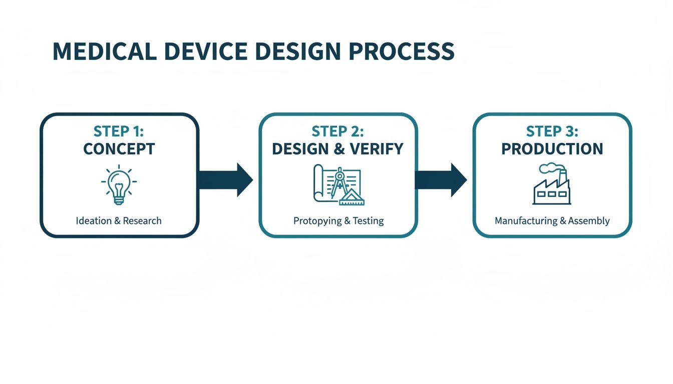
This flow highlights how decisions made in the concept phase have a direct and significant impact on the rigor required during design, verification, and the eventual production ramp-up.
Experienced teams understand these are not discrete, sequential stages but deeply interconnected activities. For instance, decisions about manufacturability (DFM) must happen during the initial design phase, not after a prototype is built. A clear verification strategy has to inform the design inputs from the very beginning. Neglecting this integration is a classic failure mode that leads to schedule overruns and budget-draining rework. High-performing teams build their entire process around a unified approach, ensuring that design for manufacturability is a core principle from day one, not an afterthought.
The core discipline of designing medical devices is building a traceable, defensible record of engineering decisions. It’s about proving not only that the device works but that it was built correctly and safely according to a plan.
To bring this lifecycle into sharper focus, the table below outlines the key stages, their objectives, and the critical outputs required at each step.
Key Stages and Outputs in Medical Device Development
| Development Phase | Primary Objective | Key Deliverables |
|---|---|---|
| 1. Concept & Feasibility | Define the user needs, intended use, and business case. Assess technical and market viability. | User Needs Document, Initial Risk Analysis, Market Requirements Document, Feasibility Study Report. |
| 2. Design & Development | Translate user needs into system requirements and detailed design specifications. | Design & Development Plan, System/Software Requirements, Design Specifications (Hardware, Software, Mechanical), Design History File (DHF) initiated. |
| 3. Prototyping & Iteration | Build functional prototypes to test design concepts and gather user feedback. | Functional Prototypes (Alpha/Beta units), Formative Usability Reports, Updated Design Specifications. |
| 4. Verification & Validation | Prove the design outputs meet the design inputs (Verification) and that the device meets user needs (Validation). | Verification Test Protocols & Reports, Validation Test Protocols & Reports (including Clinical/Usability), Final Risk Management File (RMF). |
| 5. Regulatory Submission & Approval | Compile all documentation into a submission package for regulatory bodies (e.g., FDA, Notified Body). | 510(k), De Novo, or PMA Submission; CE Mark Technical File; Regulatory Clearance/Approval. |
| 6. Production & Launch | Transfer the design to manufacturing, establish quality control, and release the product to the market. | Device Master Record (DMR), Process Validation (IQ/OQ/PQ), Finalized Device History File (DHF), Post-Market Surveillance Plan. |
This table serves as a high-level roadmap, illustrating the documented, evidence-based trail that must be created to move from an idea to a compliant, market-ready medical device.
The stakes are only getting higher. The global medical device design services market, valued at USD 12.79 billion in 2025, is projected to hit USD 36.25 billion by 2033. The designing and engineering segment alone commanded nearly 39% of this market, a clear signal that companies are increasingly outsourcing to expert firms that can manage FDA and EU MDR requirements while accelerating timelines. You can read the full research on Grand View Research to understand the market forces at play.
This trend highlights the immense value of development partners who can provide full-stack hardware, firmware, and software integration under a single, accountable lead. By embracing a disciplined, systems-level approach, engineering leaders can significantly reduce program risk and deliver innovative products that meet both regulatory standards and market needs.
Navigating the Regulatory and Standards Maze
For many engineering teams, regulatory compliance is the final, dreaded hurdle—a bureaucratic tax paid at the end of a project. This is a catastrophic mistake. Trying to slap compliance onto a finished device is a surefire recipe for costly rework, painful delays, and endless frustration.
The right way to think about it? Standards aren't a checklist. They are the very framework for building a safer, more reliable device from day one.

This proactive mindset changes everything. It turns abstract rules into concrete engineering requirements. More importantly, it ensures every design choice is defensible and traceable, building your Design History File (DHF) organically as you go—not in a panicked scramble right before an audit.
The Three Pillars of Medical Device Compliance
The regulatory world can feel like an alphabet soup of acronyms, but a few key standards form the bedrock of almost every medical device program on the planet. If you understand what they do, you're halfway to building a compliance-by-design culture.
ISO 13485 (Quality Management Systems): This is the backbone of your entire operation. It's not just about the device; it's about your organization. ISO 13485 requires you to have a documented Quality Management System (QMS) that governs everything—design controls, risk management, supplier qualification, you name it. It’s how you prove you have the processes to consistently deliver safe and effective products.
ISO 14971 (Risk Management): This is where you put on your pessimist hat. ISO 14971 forces you to systematically ask, "What could possibly go wrong?" and then design concrete solutions to prevent that harm. It's a living process of identifying, analyzing, and controlling risks throughout the device's entire lifecycle, not a one-and-done document.
IEC 60601 (Medical Electrical Equipment): If your device plugs into a wall or has a battery, this family of standards is non-negotiable. It covers the essential safety and performance needed to prevent hazards like electrical shock, burns from high temperatures, or electromagnetic interference (EMC). Failing to design for IEC 60601 from the start can force a complete—and completely avoidable—product redesign.
For technical leaders, the goal isn't to become a regulatory lawyer. It's to translate these standards into engineering requirements your team can actually build and test against. Compliance simply becomes another critical variable in the complex equation of system design.
Translating Regulations Into Engineering Workflow
The real magic happens when you embed these standards into your day-to-day engineering sprints and project milestones. This is where you move from thinking about compliance as paperwork to seeing it as a set of hard design constraints.
For example, your ISO 14971 risk file might identify a critical failure mode: a software bug could cause a therapy-delivery pump to overdose a patient. That risk doesn't just sit in a document; it immediately creates a non-negotiable engineering requirement. You might decide to implement a hardware watchdog timer, completely independent of the main processor, that acts as a physical fail-safe.
This entire chain—the risk, the analysis, the mitigation, and the verification—must be meticulously documented in the DHF. This creates a perfect, traceable link from a potential harm all the way down to a specific component on your PCB.
Likewise, ISO 13485 mandates formal design reviews. Don’t treat these as casual check-ins. Your program manager should structure them as hard gates in the project plan, perhaps at the end of your EVT build. To pass the gate and move on, the team must meet a predefined list of criteria. This prevents the "soft gates" that let teams kick the can down the road, accumulating technical debt that becomes impossible to pay off later.
Choosing Your FDA Pathway
Your regulatory strategy, timeline, and budget will be dictated by your device's classification, which is based entirely on its level of risk. In the U.S., the FDA approval process for medical devices offers a few distinct routes.
| FDA Pathway | Typical Device Class | Key Requirement | Timeline & Cost |
|---|---|---|---|
| 510(k) Premarket Notification | Class II (Moderate Risk) | Demonstrate "Substantial Equivalence" to a legally marketed predicate device. | 3-6 months, lower cost. |
| De Novo Classification | Class I/II (Low-Moderate Risk) | For novel devices with no valid predicate; establishes a new classification. | 6-9 months, moderate cost. |
| Premarket Approval (PMA) | Class III (High Risk) | Prove safety and effectiveness through extensive data, often including clinical trials. | 1-3+ years, highest cost. |
Picking the wrong pathway can burn years of time and millions of dollars. An early, honest assessment of your device’s novelty and risk profile is absolutely essential for building a realistic program plan and budget. This single decision has a massive ripple effect, directly shaping the scope and rigor of all your future verification and validation activities.
Implementing Robust Design Controls and Risk Management
At the heart of every successful medical device lies a non-negotiable foundation: robust Design Controls (as mandated by FDA 21 CFR 820.30) and a proactive risk management process (guided by ISO 14971). It's easy for teams to see these as just more regulatory paperwork, but experienced leaders know the truth. This is the essential engineering discipline that connects a user’s need to a safe, effective, and compliant final product.
Think of it as the auditable proof of your engineering diligence.
Skipping or short-changing this framework is one of the fastest ways to guarantee project failure. It leads to chaotic development cycles, embarrassing regulatory rejections, and worst of all, devices that are either unsafe or simply don't solve the problem they were designed for. This structured approach forces clarity, accountability, and traceability from day one.
Building the Traceability Chain
The design control process creates a "waterfall" of documentation where each stage flows logically from the one before it. This creates a clear, unbroken, and traceable path from a simple user idea to a fully validated device. This traceability matrix isn't just a good idea—it’s the cornerstone of your Design History File (DHF) and is absolutely essential for passing any regulatory audit.
The process follows a very specific sequence:
User Needs: It all starts here. These are high-level, plain-language statements about what the device must do for the person using it. For instance: "The user must be able to monitor their blood glucose levels continuously for 7 days without needing to recharge the device."
Design Inputs: This is where engineers translate the user need into concrete, testable specifications. They must be measurable and completely unambiguous. The user need above might become a design input like: "The device shall operate for a minimum of 168 hours on a single full charge under typical use conditions."
Design Outputs: This is your device’s "recipe"—the complete set of instructions for building it. This includes all the drawings, schematics, source code, and material specifications. The design outputs are the direct result of your engineering work to meet the design inputs.
Verification: This step answers a simple question: "Did we build the device right?" It’s all about testing to confirm that your design outputs (the recipe) actually meet your design inputs (the specifications). For our example, this means running a formal test protocol to measure the battery life of several units to prove they last at least 168 hours.
Validation: The final, crucial question is, "Did we build the right device?" This step confirms that your finished product actually meets the original user needs in its real-world environment. This could involve usability studies with actual patients to confirm that a 7-day battery life is truly practical and sufficient for their lifestyle.
This unbroken chain from User Need to Validation is the very essence of design control. It ensures that every feature you build has a purpose, every risk has been considered, and the final product is both safe and effective for the people who need it most.
A Scenario with a Wearable Diagnostic
Let's make this more concrete. Imagine your team is building a connected wearable patch for post-operative cardiac monitoring. A key user need is that "the device must reliably alert a remote clinician within 60 seconds if a dangerous arrhythmia is detected."
Design Input: This single user need gets broken down into several hard engineering requirements. For example: "The firmware algorithm shall detect ventricular tachycardia with 99.5% sensitivity and 98% specificity," and "The BLE/cellular module shall transmit a critical alert packet to the cloud server within 5 seconds of arrhythmia detection."
FMEA-Driven Design: During your Failure Modes and Effects Analysis (FMEA), the team identifies a critical failure mode: what if a software crash completely disables the detection algorithm? The Risk Control here becomes a new design requirement: you must implement an independent hardware watchdog timer that automatically reboots the system if the main application hangs. This is a direct, traceable mitigation born from rigorous risk analysis.
Verification: Now, the team writes and executes formal test protocols. One test involves feeding simulated ECG signals into the device to prove the algorithm meets its sensitivity and specificity targets. Another test deliberately crashes the software to prove the watchdog timer correctly reboots the device. These tests generate objective evidence that goes straight into the DHF.
Validation: Finally, the device undergoes simulated-use testing. Real clinicians interact with the complete system to confirm that alerts are received promptly and are clinically actionable. This proves the device not only meets its specs but works as intended in its operational context.
The market for such innovations is expanding rapidly. The connected medical device space is projected to grow from USD 75.99 billion in 2025 to USD 152.71 billion by 2030. But this growth isn't without its challenges; cybersecurity flaws were responsible for a staggering 20% of medical device recalls in 2024, a powerful reminder of the need for this level of rigor. As you can discover in more detail from Medical Micromolding, this trend underscores exactly why embedding design controls and testability from the very first concept to final compliance is absolutely critical.
How to Integrate Hardware, Firmware, and Software
Modern medical devices aren't just pieces of hardware anymore. They're complex, integrated systems where the hardware, firmware, and software absolutely must work together as a single, flawless unit. From my experience, the single most common point of failure in developing these products is the handoff between siloed engineering teams.
It’s a classic, painful story: the hardware team finishes a prototype and tosses it "over the wall" to the firmware group. They struggle with it, eventually pass it to the software team, and what you get is an integration nightmare. This broken process is a surefire recipe for blown schedules, endless rework, and a mountain of unexpected costs.
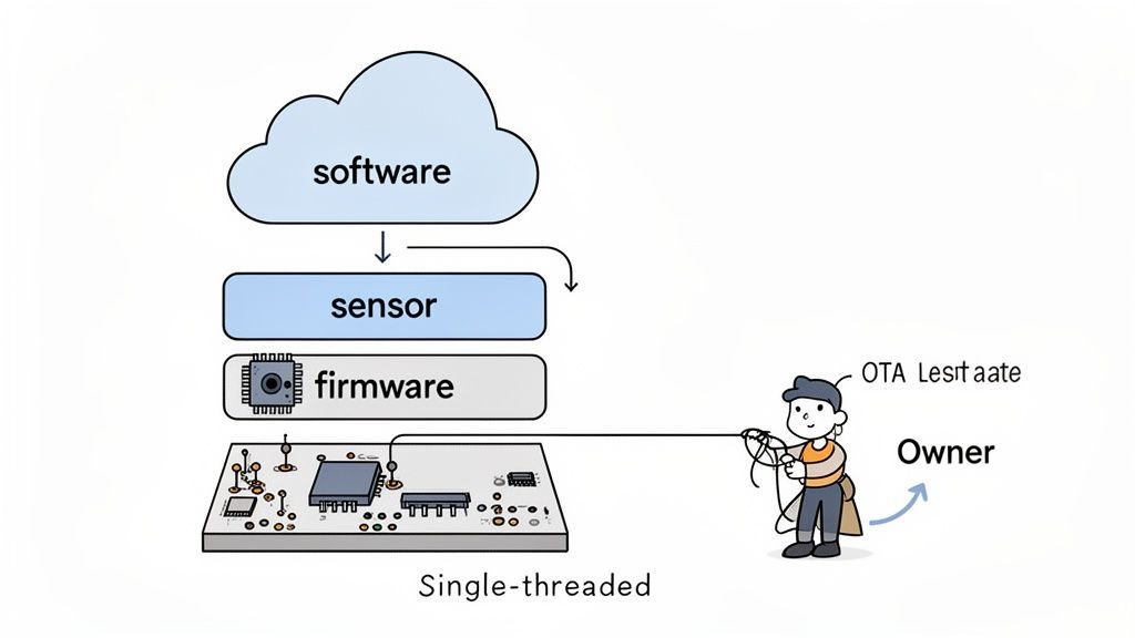
High-performing teams flat-out reject this fragmented model. They champion a unified systems engineering approach, often led by a single-threaded technical owner who is accountable for the entire stack. This structure forces the system to be co-designed from the very beginning, not just bolted together at the end.
Strategies for Unified System Co-Design
Integrated design simply means making interdependent decisions early and often. It's about thinking of the product as one complete system, where a choice in one domain has a direct, predictable impact on another. For example, deciding on the sensitivity of a sensor's analog front-end directly dictates how complex the signal processing algorithms in the firmware will need to be.
Here are a few core strategies that make this work:
- Joint Architecture Reviews: Before a single line of production code is written or a schematic is finalized, get everyone in a room. All teams—hardware, firmware, software, and QA—must review and formally sign off on the system architecture. This is where you hammer out the boundaries, interfaces, and communication protocols between all the moving parts.
- Interface Control Documents (ICDs): Think of an ICD as the non-negotiable "contract" between the hardware and the firmware. It needs to explicitly define every single register map, control signal, timing requirement, and data format. This document becomes the source of truth and prevents the kind of integration failures that come from mismatched assumptions.
- Hardware Abstraction Layers (HALs): The firmware team’s first job should be to build a robust HAL. This layer effectively decouples the application logic from the specific hardware underneath. Doing this allows the software team to get a massive head start, progressing in parallel using simulators or dev kits long before the final production hardware is even available.
On the software side of the house, adopting rigorous approaches like Clean Architecture principles can dramatically improve the maintainability of the code and reduce risks down the road. These methodologies enforce a clear separation of concerns, which makes the system far easier to test, validate, and modify without breaking core logic—an absolutely critical feature for any regulated medical product.
Architecting for Testability from Day One
Here's a hard truth: a system that can't be easily tested cannot be reliably verified. When you're designing a medical device, testability isn't a "nice-to-have" feature. It is a fundamental architectural requirement that has to be planned from the very beginning. This demands an integrated approach, because your testability hooks and features need to be embedded across the entire stack.
A common failure mode is treating testing as a final phase conducted by a separate QA team. Effective teams design for testability as an integral part of the engineering process, ensuring hardware, firmware, and software are built to be verifiable from the start.
This unified mindset ensures that testing isn’t an afterthought but a continuous, ongoing activity. It's a philosophy we live by at Sheridan Technologies; for a deeper dive, you might be interested in our guide on what is embedded systems engineering, which explores many of these concepts in more detail.
Here’s a practical look at how you build testability into each layer of your design:
| System Layer | Testability Feature | Business Impact |
|---|---|---|
| Hardware | Dedicated test points for critical signals (power rails, clocks), JTAG/SWD access for debuggers, and boundary scan capabilities. | Reduces PCB bring-up time from weeks to days. Enables automated manufacturing tests, increasing factory throughput and catching defects early. |
| Firmware | Command-line interface (CLI) for querying status and controlling peripherals, built-in self-tests (BISTs), and configurable logging levels. | Allows engineers to isolate faults quickly without a debugger. Provides critical data for failure analysis and field diagnostics. |
| Software | Comprehensive unit and integration tests, mock objects for hardware dependencies, and a robust Continuous Integration (CI) pipeline. | Catches bugs automatically before they merge into the main codebase. Enables rapid, low-risk iteration and simplifies regression testing. |
By planning these features in unison, you create a system that is far more than just a collection of working parts. You build a truly verifiable and maintainable product. This integrated discipline is the key to de-risking the complete technical stack and delivering on the promise of safe and effective medical device design.
Designing for Manufacturing and Testability
Here's a hard truth of medical device development: a brilliant prototype that works perfectly on your bench but can’t be reliably manufactured at scale is a commercial failure. So many promising projects hit a wall right here, at the transition from R&D to production. The result is almost always a painful cycle of costly redesigns that demolishes budgets and timelines.
This is why experienced teams don't wait. They build a bridge between the lab and the factory floor from day one by integrating Design for Manufacturability (DFM) and Design for Test (DFT) into the earliest stages of the project.
These aren't about dumbing down your design or making compromises. They're about making your design robust, repeatable, and profitable. Integrating these principles means every tactical choice—from component selection and PCB layout to the mechanical enclosure design—is made with a strategic business impact in mind. The payoff is a lower cost of goods, better production yields, and a smooth, predictable ramp-up with your Contract Manufacturer (CM).
Building a Comprehensive Manufacturing Test Plan
Think of a manufacturing test plan as the quality control blueprint for your assembly line. It’s far more than a simple "pass/fail" check at the very end. A solid plan is a multi-stage strategy designed to catch defects at the earliest—and therefore cheapest—point possible. A weak one leads directly to low yields, high scrap rates, and the nightmare scenario of faulty devices reaching patients.
A robust test plan has several layers:
- In-Circuit Test (ICT): Right after the PCBs are assembled, an ICT fixture, often called a "bed of nails," checks for assembly errors like shorts, opens, and incorrect component values. This is your first line of defense against fundamental manufacturing mistakes.
- Board-Level Functional Test: Next, we power up the board. This step uses automated scripts to verify that core functions are working as expected—things like power regulation circuits, processor boot-up, and communication with peripherals.
- System-Level Test: Once the device is fully assembled, we put it through its paces. This test simulates real-world use to confirm that all the hardware, software, and mechanical subsystems are working together just as the design intended.
- Final Quality Assurance (QA): The last look before boxing it up. This final step includes visual checks for any cosmetic defects, verification of proper packaging, and ensuring all labeling is correct. It's the last gate before your product ships.
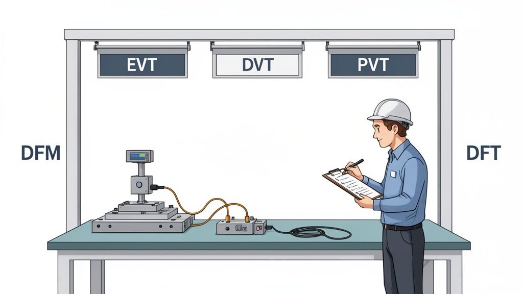
Navigating the EVT, DVT, and PVT Gates
The journey from a single prototype to mass production is governed by three critical build phases. These aren't just informal check-ins; they are formal gates that determine if a design is mature enough to move forward, preventing costly problems from advancing down the line.
Engineering Validation Test (EVT): This is your first real build, usually just 10-50 units. The goal here is simple: verify that the core design meets its fundamental requirements. EVT units are often ugly—they might have hand-soldered wires and 3D-printed parts—but they prove the architecture works.
Design Validation Test (DVT): Now things get serious. A DVT build is much larger, typically 50-200 units, and uses production-intent parts and manufacturing processes. The focus shifts to comprehensive verification against all specifications: electrical, mechanical, environmental, and regulatory. This is where you lock down the final design.
Production Validation Test (PVT): This is the final dress rehearsal. The PVT build involves hundreds or even thousands of units rolling off the actual production line. The objective isn't to validate the design anymore; it's to validate the manufacturing process itself. We're qualifying the assembly line, testing the fixtures, and ensuring the CM can build your device at volume, on time, and to spec.
The impact of getting this right is huge. The diagnostic imaging sector, which accounts for a massive 20% of the total medical device market, shows how a DFM ethos accelerates the path from concept to verification. A structured approach can reduce scrap rates by as much as 25%.
To truly optimize for the entire product lifecycle, it's also crucial to consider topics such as advancing medical device sustainability. Our team helps clients navigate these complex builds, and you can learn more about our process by reading our guide on what is design for manufacturing. Thinking about DFM and DFT from the beginning isn't just good engineering—it's a critical business strategy for any team that's serious about successfully launching a medical device.
What are the most common mistakes in medical device design?
Over the years, we've seen the same critical questions come up again and again on medical device programs. Getting the answers wrong isn't just a minor setback; it's the kind of misstep that leads to failed audits, blown budgets, and market delays that can kill a product before it ever launches.
Let's cut through the noise and tackle some of the most common mistakes and questions we hear from engineering leaders.
What Is the Biggest Mistake Teams Make When Designing a New Medical Device?
Without a doubt, the single most common and costly mistake is treating regulatory compliance and Design for Manufacturability (DFM) as activities you'll "get to later." Too many teams get completely absorbed in the core technology, chasing that perfect algorithm or elegant mechanical design.
They push compliance and manufacturing concerns to the end of the project, only to have a brutal wake-up call. They discover their documentation is nowhere near ISO 13485 compliance, or that their brilliant prototype is a nightmare to build consistently at scale.
This reactive approach almost always ends in disaster. It forces painful, expensive redesigns and can stretch a project timeline by months, if not years.
The most costly mistake is treating regulatory compliance and Design for Manufacturability (DFM) as afterthoughts. This forces expensive redesigns and extends timelines by months.
High-performing teams do the exact opposite. They operate with a "compliance-by-design" philosophy from day one. Regulatory and manufacturing experts aren't consultants brought in at the end; they're embedded in the core development team from the start.
This means every single design decision gets filtered through the critical lenses of risk (ISO 14971), user needs, and the hard realities of production. The Design History File (DHF) isn't a mountain of paperwork you scramble to assemble before an audit. It’s a living, breathing record that grows with every engineering sprint.
How Does Risk Management Practically Influence Engineering Design?
Think of risk management under ISO 14971 as a powerful engineering tool, not a bureaucratic box-ticking exercise. When done right, it's a systematic process that directly forces specific, concrete design choices.
It all starts with identifying potential hazards—any potential source of harm. This could be an electrical shock, an incorrect drug dose from an infusion pump, or a misleading reading on a diagnostic display.
For every hazard you identify, the engineering team has to dig into its potential causes, often using a structured method like a Failure Modes and Effects Analysis (FMEA). This is where risk management stops being theoretical and starts dictating the actual design.
Let’s walk through a real-world example. Imagine your FMEA for a new ventilator identifies a critical failure mode: a software crash could cause the system to lock up, preventing a life-critical alarm from sounding.
- Risk Analysis: The team analyzes this scenario, determining both the severity (catastrophic) and probability. They rightly conclude the risk is unacceptably high.
- Risk Control: This analysis now mandates a specific design mitigation. The engineers decide to implement a hardware watchdog timer—a completely independent circuit that monitors the main processor. If it detects the software has become unresponsive, it will automatically force a system reboot.
- Verification and Documentation: The team then has to actually build the watchdog timer into the hardware, write a formal test to prove it works as designed, and document the entire trail. From the initial hazard identification all the way to the verified solution, everything is recorded in the risk management file.
This creates a perfect, auditable, and traceable link between a potential harm to a patient and the specific engineering feature built to prevent it. That's risk management in action.
What Are the Key Differences Between Verification and Validation?
These two terms get used interchangeably all the time, but confusing them is a classic mistake that can create major holes in your design controls and get your regulatory submission rejected. They are two very distinct, equally critical processes.
Verification asks: "Did we build the device right?"
- Focus: This is an objective, evidence-based process. You're confirming that your Design Outputs (the finished product, its schematics, its code) actually meet your Design Inputs (the technical specifications).
- Method: This involves bench testing, inspections, and analysis against your spec sheet.
- Example: A design input specifies your device's battery must last for 10 hours of continuous use. Verification is the formal test protocol where you take a batch of devices, run them until the batteries die, and document that they all met or exceeded that 10-hour requirement.
Validation asks: "Did we build the right device?"
- Focus: This process confirms that the final, market-ready device actually meets the intended User Needs when used in its real-world environment.
- Method: This is where you put the device in the hands of actual end-users. Think clinical trials, or simulated-use testing with surgeons, nurses, or patients.
- Example: Your device has been verified to have a 10-hour battery. Great. But validation asks if 10 hours is actually enough for a clinician to complete their entire workflow without the device dying mid-procedure.
You can have a device that is 100% verified—it meets every single technical specification perfectly—but still completely fail validation because it doesn't actually solve the user's problem in a practical way. Understanding this distinction is absolutely fundamental to creating products that are not only technically sound but also clinically useful and commercially successful.
At Sheridan Technologies, we help engineering teams navigate these complex questions with confidence. Our full-stack, single-threaded ownership model ensures that regulatory strategy, risk management, and DFM are integrated into your program from day one, not bolted on at the end. If you're planning a new medical device or need to de-risk a program that's gone off track, request a design review with our experts.