Designing a medical device isn't just an engineering challenge; it’s a high-stakes program where a single misstep in design, risk management, or manufacturing readiness can lead to catastrophic budget overruns, crippling delays, and unacceptable patient risk. Ignoring the integrated nature of this process is the fastest way to get a product rejected by regulators or a factory floor filled with scrap.
This guide is for the operators and decision-makers in the trenches: VPs of Engineering, Program Managers, and Lead Engineers responsible for transforming a concept into a compliant, manufacturable, and commercially viable medical product. This is not for teams seeking business strategy or marketing advice. We will focus on the operational execution required to ship a complex medical device successfully.
This field-tested playbook provides a clear path through the development lifecycle, focusing on how to de-risk your program by integrating regulatory strategy and manufacturing readiness from day one. You'll learn how to:
- Systematically de-risk your program through structured verification and phase-gates.
- Implement robust design controls that satisfy ISO 13485 and FDA requirements.
- Design for testability and manufacturability (DFT/DFM) to ensure a smooth production ramp.
The High-Stakes World of Medical Device Design
The stakes—and the opportunity—in medical device development have never been higher. The global medical device market was valued at USD 685.11 billion in 2025 and is on track to hit USD 1,107.35 billion by 2032. This growth is fueled by an influx of investment, often led by clinicians in venture capital who understand the clinical need, and by powerful technology shifts like the trends driving IoT healthcare solutions.
However, the path from a brilliant idea to a market-ready product is littered with operational risks. A common failure mode is treating regulatory compliance, design, and manufacturing as sequential, siloed activities. High-performing teams know better. They operate with an integrated mindset, understanding that a design choice made in the first week can have massive consequences for manufacturing yield and regulatory approval months or years later.

This guide provides a structured approach to navigate this complexity, focusing on the critical execution details that determine success or failure.
Building Your Regulatory and Quality Foundation
Treating regulatory compliance as a late-stage checklist is a classic, and often catastrophic, mistake. The most successful teams view compliance as the bedrock of their program, weaving standards like ISO 13485 into the fabric of their engineering process from the first architectural sketch. This isn't about "doing paperwork"; it's about building a fortress of safety and efficacy by design. Your goal is to create a living system that produces a clear, traceable story for auditors, where every design decision is justified and every potential risk has been methodically controlled.
Core Standards That Anchor Your Design Process
While the regulatory world can feel like a labyrinth, a handful of key international standards provide the universal language for medical device quality and safety. For any team stepping into this arena, understanding their purpose isn't just helpful—it's non-negotiable.
Here’s a look at the essential standards that will guide your design journey.
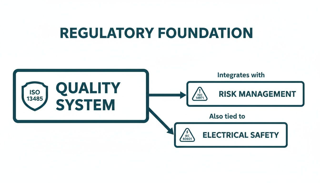
| Standard | Primary Focus | Application in Design Process |
|---|---|---|
| ISO 13485 | Quality Management Systems (QMS) | Establishes the overall operational framework for design, development, risk management, and production. It's your "how we do things" rulebook. |
| ISO 14971 | Risk Management | Mandates a continuous process to identify, analyze, evaluate, and control all potential risks associated with the device, from concept to disposal. |
| IEC 62304 | Software Lifecycle Processes | Governs the entire lifecycle for medical device software and firmware, from requirements and architecture to testing, release, and maintenance. |
| IEC 60601 | Medical Electrical Equipment | Addresses the fundamental safety and essential performance of devices with electrical components, covering hazards like shock, EMC, and mechanical stability. |
Think of these standards not as obstacles, but as your roadmap. They provide a structured, internationally recognized framework for demonstrating that you've built a high-quality, safe, and effective product.
Choosing Your Path to Market
The regulatory pathway you select has a massive impact on your project's timeline, budget, and data requirements. While frameworks differ globally, the two most common jurisdictions are the U.S. and the European Union, each with its own distinct process.
In the U.S., the Food and Drug Administration (FDA) has three primary routes for bringing a device to market:
The 510(k) pathway is the most common, used for Class II devices that are "substantially equivalent" to an existing, legally marketed device (a predicate). This requires demonstrating your device is as safe and effective as the predicate.
For novel Class I or II devices that have no existing predicate, the De Novo process provides a route to market. The most intensive and rigorous path is the Premarket Approval (PMA). This is reserved for high-risk Class III devices and demands extensive clinical data to independently prove safety and effectiveness.
The EU's Medical Device Regulation (MDR) has its own classification rules and conformity routes that are equally complex. Making the right strategic choice early on is absolutely critical. For a more thorough breakdown, our detailed guide on the FDA approval process for medical devices can provide deeper clarity on navigating these crucial decisions.
Implementing Robust Design Controls
If regulatory standards are the steel frame of your medical device, then Design Controls are the architectural blueprints that bring it to life. This framework, laid out by the FDA in 21 CFR 820.30, is the operational heartbeat of any successful development program. It's the disciplined, traceable process that methodically turns an idea into a real, verifiable device. Trying to build a medical product without it isn't just a bad idea—it's a direct route to failed audits, chaotic scope creep, and a device that ultimately fails its users.
And the pressure to get this right has never been higher. The market for medical device design services is on track to hit USD 9,392.5 million by 2030, driven by a blistering 13.8% growth rate from 2025. This isn't just about building more devices; it's about building more complex devices that require expert engineering to manage integrated systems and navigate compliance from the very first sketch. You can read the full research about these market dynamics to get a sense of the competitive landscape.
From User Needs To Design Outputs
The whole Design Controls process kicks off with a deceptively simple step: capturing User Needs. Think of these as high-level stories about what the device needs to accomplish from the viewpoint of the people who will actually use it—the patient, the doctor, the at-home caregiver. They are intentionally written in plain language, focusing entirely on the "what," not the "how."
From there, the engineering team gets to work translating those stories into Design Inputs. This is where the magic really starts. We take those qualitative needs and distill them into quantitative, testable engineering requirements that will form the backbone of your System Requirements Document (SRD).
- User Need: "An elderly patient with arthritis has to be able to use the device easily by themselves."
- Design Input: "The device shall have a total weight of less than 500 grams. The main activation button shall require no more than 5 Newtons of force to press. The primary display font must be at least 18 points."
This translation step is a notorious minefield. Vague, fuzzy inputs inevitably lead to a design that misses the point and verification tests that can't produce a clean pass or fail. The best engineering teams are absolutely obsessed with getting this right, ensuring every single requirement is crystal clear, verifiable, and can be traced directly back to a specific user need.
This entire process doesn't happen in a vacuum. It's all built on a foundation of core regulatory standards for quality, risk, and safety.
Think of your Design Controls as the engine that drives your project forward, while these standards are the road and guardrails that keep you on a compliant path.
The Role of Integrated Systems Engineering
With solid Design Inputs in hand, your team begins creating Design Outputs. This is the tangible "proof" of the design work—all the schematics, the source code, the mechanical drawings, the material specs, and the assembly instructions that define exactly what your device is and how it's made. Crucially, every single Design Output has to connect directly back to a Design Input.
This traceability is where many projects, especially complex mechatronic ones, start to fall apart. When you have silos between the hardware, firmware, and software teams, you often end up with a pile of parts that don't talk to each other, creating a fragmented system that simply doesn't work as intended.
The most effective way to head off these integration disasters is to have a single-threaded technical owner who has authority across all disciplines. This person’s job is to ensure the Design Outputs from different teams come together to form a cohesive, functional system—not just a collection of individually correct components.
This integrated approach is a cornerstone of the Sheridan POV. It smashes the "throw it over the wall" friction that plagues so many traditional development models. When the firmware team makes a decision, the hardware team knows about it and accounts for it instantly.
Design Reviews: The Critical Phase-Gates
Finally, you have Design Reviews. These are the formal, non-negotiable checkpoints in your project. These are not casual status meetings. They are rigorous, fully documented reviews held at the end of each major phase (like concept, architecture, or pre-DVT). Their entire purpose is to confirm three things:
- The design actually meets all of its input requirements.
- Every risk that has been identified has been addressed and mitigated.
- The project is genuinely ready to move on to the next phase.
A classic mistake is to treat these reviews as a simple rubber-stamping exercise. That’s a huge error. Smart teams see them for what they are: critical risk-reduction gates. A proper Design Review always includes an independent reviewer—someone who wasn’t directly involved in that phase of the work—to provide a fresh, objective pair of eyes. Cutting corners on these reviews is a false economy that almost guarantees you’ll discover expensive problems much later, when they are exponentially harder and more costly to fix.
Executing a Strategic Verification and Validation Plan
In medical device development, prototyping is not a chaotic bug hunt; it is a disciplined, phased approach to generating evidence known as Verification and Validation (V&V). This process revolves around a series of builds with very specific jobs: Engineering Validation Test (EVT), Design Validation Test (DVT), and Production Validation Test (PVT). These aren't just corporate jargon. They represent distinct stages of product maturity, each with clear entry and exit criteria that feed directly into your Design History File and risk management activities. Shortcutting this progression is a recipe for discovering a fatal flaw far too late, forcing painful redesigns and derailing your regulatory timeline.
The Purpose of Each Validation Phase
The EVT-DVT-PVT sequence is a progressive de-risking strategy designed to prove out your design, from its core architecture to its manufacturability at scale. Each phase answers a fundamental question about your product’s readiness.
Engineering Validation Test (EVT): Did we design it right? This phase uses prototype parts (e.g., 3D prints, breadboards) to prove the fundamental architecture works, confirm key performance parameters, and burn down the highest technical risks.
Design Validation Test (DVT): Did we design the right product? This is the most comprehensive testing phase. Using production-intent parts and tooling, DVT rigorously tests the device against every single design input, covering functional, environmental, and safety requirements.
Production Validation Test (PVT): Can we build it reliably at scale? This is the final gate before mass production. Using the final assembly line and operators, a small production run proves your manufacturing process is stable, repeatable, and meets all quality and yield targets.
Think of it this way: EVT proves your architect's blueprint is sound. DVT confirms the building constructed from that blueprint can withstand every specified earthquake and hurricane. PVT proves the factory can build that exact same high-quality building over and over again without a single deviation.
A Real-World Scenario: A Connected Handheld Diagnostic
Let's make this concrete with an example: a new connected, handheld diagnostic device. It uses an optical sensor to analyze a disposable test cartridge and then wirelessly sends the results to a clinician's tablet. The stakes are sky-high—a false negative could lead to a missed diagnosis and patient harm.
The V&V plan for a device like this has to be meticulously structured to build a solid case of evidence at each stage.
EVT Phase Focus:
The EVT build is all about tackling the scariest technical risks head-on. For our diagnostic device, the team would be laser-focused on a few key areas:
- Core Functionality: Does the optical sensor and its analog front-end meet the required sensitivity and signal-to-noise ratio to get a clean reading?
- Architectural Choices: Can the microcontroller we picked actually run the analysis algorithm fast enough while also managing the Bluetooth LE stack without crashing?
- Power Budget: Does our battery and power management circuit provide enough juice to meet the User Need of "lasting a full 12-hour hospital shift"?
The exit gate for EVT would be a test report showing these core systems work as designed. It doesn't matter if the case is a rough 3D print and the firmware is still buggy—the core architecture is proven.
DVT Phase Focus:
The DVT phase is an all-out assault on your requirements document. Using the final injection-molded casings from production tooling and the final PCBAs from your contract manufacturer (CM), the test plan explodes in scope.
| Test Category | Key Verification Activities |
|---|---|
| Electrical Testing | Full EMC/EMI testing to IEC 60601-1-2 standards, battery cycle life testing, power integrity under various loads, and ESD testing. |
| Firmware Testing | Unit and integration tests for all software modules, RTOS timing analysis, fault injection (e.g., simulating a sensor failure), and BLE connection stability and security testing. |
| System-Level Testing | Full system performance using the final disposable cartridges, drop and vibration testing, ingress protection (IP) testing, and running through every single user workflow. |
| Validation | Formative usability studies to ensure clinicians can operate the device without error, confirming it truly meets their needs in a simulated use environment. |
Passing the DVT gate means you have objective evidence that your "frozen" design meets every single specification you wrote down. Any failure at this stage triggers a formal Engineering Change Order (ECO) and requires re-testing the affected part of the system.
PVT Phase Focus:
Finally, the PVT run is all about manufacturing readiness. The team would oversee a run of several hundred units down the final assembly line at the CM. The focus shifts completely from product performance to process performance. Key metrics are everything:
- Yield: What is our first-pass yield at each assembly and test station? Where are units failing?
- Repeatability: Do all units consistently pass the automated end-of-line functional test?
- Traceability: Are serial numbers being programmed correctly and tracked through the entire process?
A successful PVT run gives you the hard data to prove your manufacturing process is robust and ready, justifying the massive expense of ramping to full-scale production. This structured, evidence-based approach is what turns testing from a simple bug hunt into a strategic asset for designing medical devices that are both innovative and compliant.
If your team needs an independent review of its testing strategy, a verification plan review can be invaluable for spotting gaps before they morph into expensive, schedule-killing problems.
Designing for Manufacturing and Test
A brilliant design that can’t be built reliably at scale is a commercial failure waiting to happen. This is where the discipline of Design for Manufacturability (DFM) and Design for Testability (DFT) comes in. This isn’t a task you bolt on at the end; it's a parallel engineering effort that must be woven into the design process from the very first architectural sketch. Ignoring DFM/DFT guarantees late-stage chaos, spiraling costs, and a painful production ramp. The goal is to engineer a product that is born to be built and tested efficiently, de-risking the critical transition from DVT to mass production.
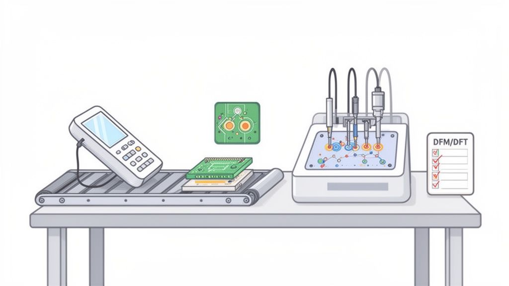
Electronics DFM and DFT Checklists
DFM focuses on making physical assembly as simple and repeatable as possible. DFT is about ensuring you can quickly and accurately prove every unit was built correctly. They are two sides of the same coin.
Key DFM Considerations for Electronics:
- Component Selection: Prioritize parts with long-term availability, multiple sources, and packaging that suits automated assembly. Avoid components requiring manual placement unless absolutely necessary.
- PCB Layout for Assembly: Ensure sufficient clearance between components to prevent solder bridging. Use standardized footprints and clear polarity markings.
- Panelization: Work with your CM to optimize the PCB panel layout for their specific line, defining V-score or tab-routing to ensure a clean, efficient de-paneling process.
Key DFT Considerations for Hardware:
- Test Point Access: Strategically place test points on all critical nets—power rails, clocks, key data lines—to allow access for automated "bed-of-nails" or flying-probe testers.
- Boundary Scan (JTAG): For complex ICs like FPGAs and microprocessors, a JTAG chain is non-negotiable. It provides a digital test access port to verify connections between chips without needing physical probes.
- Firmware Hooks: Build diagnostic routines into the firmware that a test fixture can trigger to exercise peripherals, check memory, and report status codes. This drastically simplifies functional testing on the manufacturing line.
Creating a Robust Manufacturing Test Plan
A manufacturing test plan is a multi-layered strategy designed to catch defects as early and cheaply as possible. A failure caught at the bare board level might cost a few dollars to fix; that same failure found after final assembly could cost hundreds. The plan should sequence tests logically, from component-level checks to full system verification.
- Incoming Quality Control (IQC): Your first line of defense. Verify critical components from suppliers before they enter the assembly line to catch counterfeit parts or out-of-spec batches.
- In-Circuit Test (ICT) or Flying Probe: Immediately after assembly, this automated test checks for shorts, opens, and correct component placement on the PCBA.
- Board-Level Functional Test (BFT): The PCBA is powered up and its firmware is loaded. Automated scripts use the DFT hooks to verify the board is "alive" and all core functions are working.
- System-Level Assembly and Test: The board is installed in its final enclosure, and a full system-level functional test is run to ensure all subsystems are working together correctly.
The core principle is this: A test plan isn't an afterthought; it is a design requirement. Your hardware and firmware architecture must be co-developed with the test plan in mind. If your test engineers can't access a critical signal or trigger a diagnostic mode, you have a design flaw, not just a testing inconvenience.
Innovation continues to reshape healthcare, with trends like AI-powered diagnostics holding a 32.2% tech market share in 2025. Yet, persistent quality challenges mean only 16% of pre-commercial firms are QMSR-ready, underscoring the critical need for integrated, testability-first design. For teams looking to accelerate, you can read more about these medical device industry statistics and the impact of these trends.
For engineering leaders, the message is clear. You must enforce DFM and DFT as an engineering discipline from day one. By investing in these practices early, you control the chaos of the EVT-to-DVT transition and build a product that is not just well-designed, but also well-made. To explore this topic further, you can learn more about our approach to design for manufacturing and how it reduces late-stage risk.
Getting Your Supply Chain Ready for Primetime
Your contract manufacturer (CM) and key component suppliers are an extension of your engineering team. The formal handoff from your final design to their production line is one of the riskiest transitions in the entire product lifecycle. A flawed transfer process guarantees production delays, cost overruns, and quality issues that can sink your launch. This isn't about emailing a CAD file and a bill of materials (BOM); it’s about building a transparent, resilient manufacturing ecosystem through rigorous supplier qualification, obsessive documentation, and aligned quality standards.
From Design Freeze to First Article
The moment your design is "frozen" after a successful DVT, the focus pivots to flawlessly transferring that design to your manufacturing partners. Your documentation package must leave zero room for interpretation.
It must include:
- Manufacturing Process Instructions (MPIs): Step-by-step guides for every assembly, calibration, and test procedure. Specify everything from screw torque values to the exact firmware version to be flashed.
- Supplier Quality Agreement (SQA): A binding contract defining quality expectations, inspection criteria, process controls, and the handling of non-conforming parts.
- Golden Sample: A physical unit, blessed by engineering, that represents the gold standard of an acceptable product. This serves as the undeniable on-site reference for your CM.
The rule is brutally simple: if it isn't written down and formally released through your quality system, it effectively doesn't exist. Ambiguity in your manufacturing package is the root cause of production variance and quality headaches. Top-tier teams eliminate it with ruthless discipline.
Building Your Production Test and Inspection Strategy
Your test plan must extend deep into your supply chain. An incoming quality inspection plan is your first line of defense, designed to catch bad components before they ever hit your assembly line. For a critical custom sensor, for example, your IQC process should involve pulling a sample from every batch and running it on a dedicated fixture to confirm its performance characteristics match your spec. This is how you detect a supplier’s process drift before it becomes your crisis.
At the same time, you must lock down your production line fixture strategy. Key fixtures include:
- Secure Flashing Stations: Fixtures designed to program your device’s firmware while protecting your intellectual property, often using encrypted firmware images and secure bootloaders.
- Automated Test Fixtures: "Bed-of-nails" testers or custom rigs that run functional tests, measure critical electrical parameters, and log every result automatically. Automation is essential for consistency and throughput.
- Traceability Systems: Barcode scanners and software integrated at every station to link component lot codes and test results to a specific unit’s serial number. This is critical for regulatory compliance and efficient failure analysis.
To ensure your supply chain for medical devices is agile and ready for the future, it pays to understand how emerging technologies can help. You can get a sense of what's coming by exploring warehouse management trends like AI, robotics, and 3D digital twins.
Before you greenlight mass production, a formal Manufacturing Readiness Review (MRR) is the final gate. This is a comprehensive check to ensure all systems—people, processes, and parts—are truly ready.
Manufacturing Readiness Review Checklist
This checklist is a critical tool for you and your CM to jointly assess readiness for full-scale production. It's the final gut-check before committing to major capital expenditures.
| Domain | Key Checkpoints | Status (Ready/Action Required) |
|---|---|---|
| Documentation | Final BOM, CAD files, schematics, and Gerbers released and transferred? MPIs and work instructions finalized, translated (if needed), and approved by the CM? | |
| Supply Chain & Logistics | All component suppliers qualified and under contract? Lead times confirmed and purchase orders placed for initial production run? Incoming Quality Control (IQC) plan defined and resources trained? | |
| Manufacturing Process | Production line layout finalized? All assembly jigs, tools, and fixtures built, qualified, and on-site? Process Failure Mode and Effects Analysis (PFMEA) completed? | |
| Test & Quality | Production test fixtures (e.g., programming, functional test) deployed and validated? "Golden Sample" provided to CM? First Article Inspection (FAI) plan defined? Traceability system operational? | |
| Personnel & Training | CM line operators and technicians fully trained on all MPIs and test procedures? Quality inspectors trained on inspection criteria? Key contacts established for engineering and quality support? | |
| Packaging & Shipping | Final product packaging designed and sourced? Labeling compliant with regulatory standards? Logistics for shipping finished goods to distribution centers established? |
Passing an MRR signifies that your team and your manufacturing partner are fully aligned and have mitigated the major risks associated with launching a new product. It’s the formal handshake that says, "We're ready to build."
Frequently Asked Questions About Designing Medical Devices
If you're an engineering leader or program manager staring down the barrel of a new medical device program, you’ve got questions. We get it. Here are some of the most common ones we hear, along with some straight talk based on years in the trenches.
How Long Does It Take to Design a Medical Device?
This is the million-dollar question, and the honest answer is: it depends. The timeline is a function of your device’s class, its technical complexity, and the experience level of your team. The biggest unknowns are always regulatory review cycles, the need for clinical data, and the inevitable hiccups during verification and validation.
As a rough guide:
- A simple Class I device might take a year to 18 months.
- A Class II device heading for a 510(k) submission typically requires 2-4 years from concept to clearance.
- A complex Class III device needing a full Premarket Approval (PMA) is a long haul—think 5-10+ years.
The single best way to rein in these schedules is to run an integrated development process. Getting DFM (Design for Manufacturability) input from day one is the most effective way to sidestep predictable, and costly, delays.
What Is the Most Common Failure Point in Medical Device Development?
The most common—and by far the most expensive—point of failure is a fundamental disconnect between your design, manufacturing, and regulatory strategies. Too many teams treat these as separate, sequential stages. That's a recipe for disaster.
This siloed thinking is what leads to major rework when a brilliant design proves impossible to manufacture at scale, or when your verification plan fails to generate the exact evidence the FDA needs for your submission.
High-performing teams don't work this way. They build a cross-functional team from the very beginning, insisting that manufacturing and regulatory experts are in the room for the first architecture reviews. Adopting a “design for compliance and scale” mindset is the most powerful risk-reduction strategy you have.
How Do I Budget for Medical Device Development?
Budgeting is always a challenge, but the biggest mistake we see is focusing only on the non-recurring engineering (NRE) costs. That’s just one piece of a much larger puzzle. You have to allocate a significant chunk of your budget for verification and validation, production tooling, regulatory submission fees, and any required clinical studies.
For a moderately complex Class II device, you should expect total development and testing costs to land anywhere from a few million to over $10 million. Skimping on the budget for verification, validation, or compliance readiness is a false economy. It almost always guarantees you'll spend more money and lose more time fixing problems down the road. You absolutely must budget for the entire evidence-generation process, not just the upfront design work.
At Sheridan Technologies, we help teams navigate these challenges by providing integrated engineering from architecture through production readiness. If your team is facing a complex system integration challenge or preparing for a critical design review, our experts can help you de-risk the program. Request a design review today. Learn more at https://sheridantech.io.