
Bringing complex electronics to market is a high-stakes process where a single oversight in design, testing, or supply chain can derail schedules and budgets. For a VP of Engineering, Program Manager, or Lead Systems Engineer, the pressure to execute flawlessly is immense. This guide is for leaders responsible for high-reliability hardware programs where failure carries significant business or safety consequences. This framework is less applicable for simple consumer gadgets or pure software products where physical manufacturing and supply chain risks are minimal. It provides a battle-tested roadmap for navigating NPI with technical discipline.
This guide presents a phased, systems-thinking framework to de-risk your program from concept to full-scale production. We will cover how to:
- Execute the EVT, DVT, and PVT phased-gate process with rigor.
- Integrate Design for Manufacturability (DFM) and Test (DFT) from day one.
- Implement a robust supplier and manufacturing readiness plan.
Defining Your New Product Introduction Framework
A new product introduction (NPI) for complex electronics isn't a project; it's a discipline. It’s a structured process that methodically transforms an architectural concept into a product that is not only functional but also scalable, reliable, and profitable. Success isn't born from a single brilliant idea; it’s forged through rigorous engineering, proactive risk management, and tight alignment across design, verification, and manufacturing teams. This process forces you to answer the hard questions at every stage, ensuring you’ve validated design feasibility, verification coverage, and manufacturing readiness before committing capital to the next phase.
The primary goal is to systematically de-risk the program. It’s about ensuring your product not only works as designed but can be built consistently, at cost, and at scale. Without a structured NPI framework, teams inevitably get bogged down fighting costly defects, schedule slips, and supply chain fires right when the stakes are highest—during the production ramp.
Navigating Today's NPI Challenges
The pressure to execute flawlessly has never been more intense. Recent years have seen a marked slowdown in product launches. The consumer products sector, for instance, saw a significant dip in new introductions during 2023 and 2024, creating what analysts are calling a ‘pent-up pipeline’ of products queued for 2025. This trend, often driven by budget cuts and restructuring, led even innovation powerhouses like 3M to dramatically slash their annual product output. Many companies opted for minor, iterative updates over true breakthrough innovations.
This market reality puts immense pressure on engineering and program leaders. A delayed launch doesn’t just mean losing ground to a competitor; it means missing a critical window of market opportunity that may not come again.
At Sheridan Technologies, we view NPI not as a linear checklist but as an integrated system. Every decision made during the concept phase has a direct ripple effect on manufacturing yield and field reliability. Our focus is on making those connections visible and manageable from day one.
Building a Foundation for Success
A strong NPI framework hinges on a clear definition of roles, responsibilities, and success metrics for each phase. This isn't about just creating a schedule. It’s about building a shared, crystal-clear understanding of what must be achieved to earn the right to move forward.
This guide will walk you through the key milestones and deliverables that form the backbone of a successful hardware NPI program. While we focus on the technical execution for complex electronics, the foundational principles of a structured launch apply broadly. For a comprehensive guide on the entire journey, consider learning how to launch a new product for B2B success.
Mastering The EVT, DVT, and PVT Phased Gate Process
A structured new product introduction lives or dies by its phase gates. These aren't just bureaucratic hurdles; they’re critical, go/no-go decision points that force an objective look at program risk, technical maturity, and business readiness. For complex electronics, the three most vital gates are the Engineering Validation Test (EVT), Design Validation Test (DVT), and Production Validation Test (PVT).
Getting this phased process right is what separates a smooth launch from a premature and costly ramp to production. Each stage has a distinct purpose and answers a fundamental question before you commit more resources. Moving from one phase to the next isn't automatic—it's an earned promotion for your product based on achieving specific, pre-defined exit criteria.
This flow chart gives a great high-level overview of how a product moves from a rough idea through the gauntlet of design, validation, and finally into full-scale production.
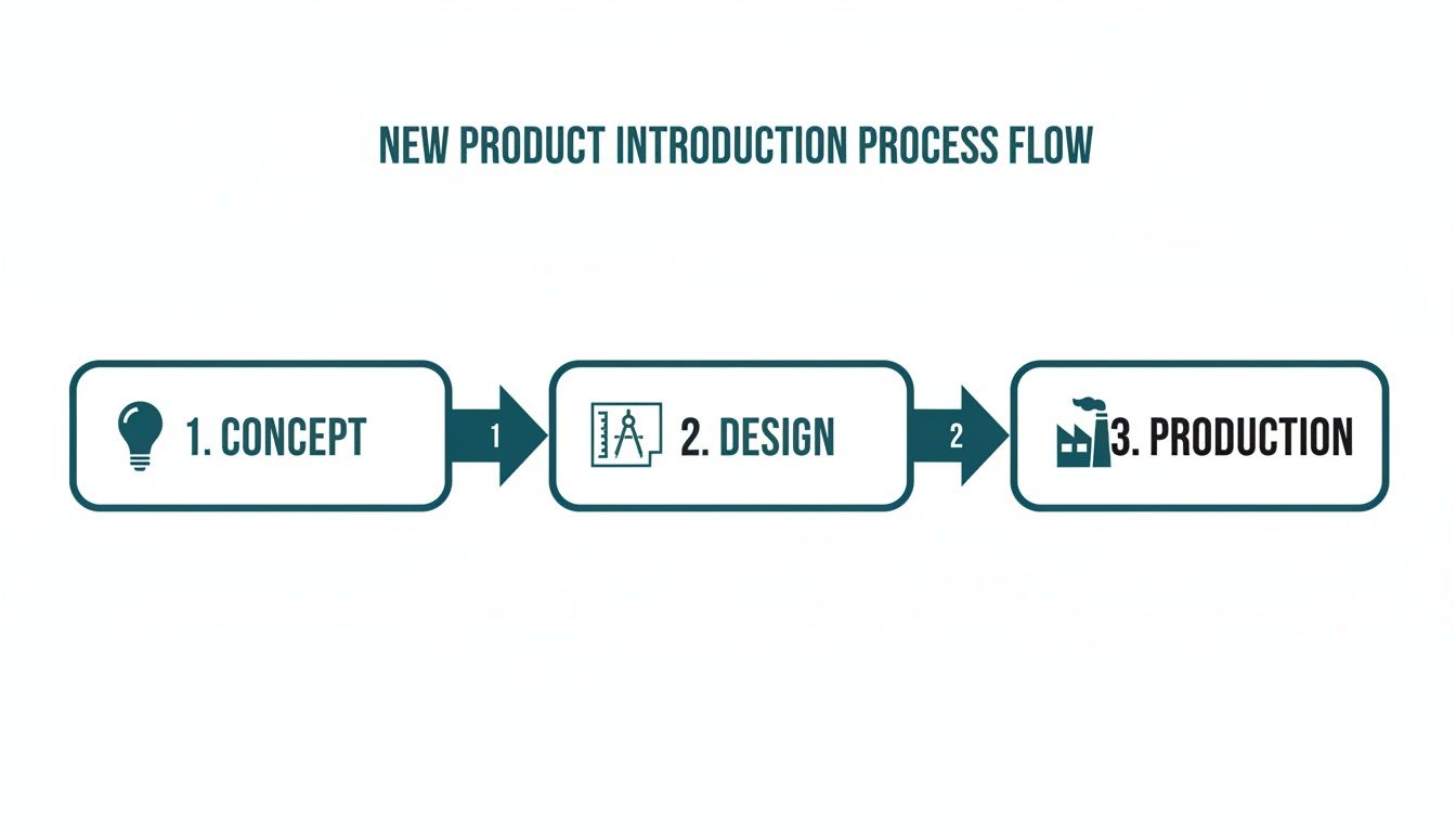
Think of it as a funnel. As you move through it, investment increases, but risk should be systematically decreasing as you validate every critical assumption along the way.
The EVT Stage: Does The Core Architecture Actually Work?
The Engineering Validation Test phase has one objective: prove that your core architectural decisions are sound. This is your first real test of the fundamental building blocks of your design—the microprocessor, key chipsets, power architecture, and core firmware. Do they perform their most basic functions together?
EVT builds are typically small (5-20 units) and often hand-assembled in the engineering lab. Forget cosmetics or comprehensive test plans. This is all about targeted, high-risk validation. You’re actively hunting for the big, "showstopper" problems: major hardware and firmware integration issues, power-on failures, and fundamental performance bottlenecks.
The goal of EVT isn't to pass every test. It's to find every major problem. A successful EVT is one that uncovers the "showstopper" bugs early, when they are cheapest and fastest to fix.
Key activities during EVT usually boil down to these:
- Board Bring-Up: Verifying power rails, clock signals, and basic peripheral communication like I2C and SPI. Can the board power on and boot?
- Architectural Validation: Stress-testing the riskiest new technology or design choices to confirm their viability.
- Preliminary Performance: Running basic functional tests to get an early signal on whether the system can hit its most critical performance targets.
Exiting EVT doesn't mean you have a bug-free device. It means you have high confidence that your core design is viable and every "Blocker" issue has a clear path to resolution before the next build. For a deeper dive into this entire journey, you can explore the full product development lifecycle stages.
The DVT Stage: Is The Design Final And Fully Verified?
The Design Validation Test phase shifts the focus from "does it work?" to "does it meet all of its requirements?" This is where your product is tested against every line item in the Product Requirements Document (PRD). At this point, the design must be "frozen," and any changes are tightly controlled through a formal Engineering Change Order (ECO) process.
DVT builds are larger (typically 50-200 units) and, critically, must be assembled using production-intent tooling and components. This phase is all about exhaustive verification and validation.
Operating Scenario: The Medical Device Signal Integrity Nightmare
A team developing a portable diagnostic device enters DVT with a design they believe is final. During environmental testing, they discover intermittent signal integrity issues on a critical analog front-end, but only at the upper end of the specified operating temperature. This is a classic DVT challenge. A panicked, undisciplined response could derail the schedule.
Instead, the program manager convenes the lead hardware, firmware, and quality engineers to execute a disciplined response:
- Containment: They immediately quarantine all DVT units and halt any further testing on that subsystem to prevent chasing ghost failures.
- Root Cause Analysis: Using an environmental chamber, hardware engineers replicate the failure while capturing detailed oscilloscope traces. They pinpoint a subtle impedance mismatch exacerbated by thermal drift in a specific passive component.
- ECO Process: The lead engineer drafts a formal ECO, detailing the analysis, proposing a change to specific component values, and assessing the impact on schedule, cost, and regulatory filings.
- Controlled Re-Spin: Once the ECO is approved, a small batch of boards is re-spun with the fix. This mini-batch undergoes accelerated, targeted re-validation before the fix is integrated back into the main DVT program. This rigid control prevents a chaotic "whack-a-mole" debug cycle from derailing the DVT effort.
The PVT Stage: Can You Actually Build It At Scale?
Finally, we get to the Production Validation Test. The question here isn't about the design anymore. It’s about your manufacturing process. Can your contract manufacturer (CM) build your product reliably, repeatedly, and at your target cost and volume?
PVT is the first "real" production run. It uses the final tooling, the final test fixtures, and the final assembly lines with fully trained operators. You’re no longer just debugging the product; you’re debugging the factory. You're measuring yield, throughput, and process capability (Cpk). All that early investment in Design for Manufacturability (DFM) and Design for Testability (DFT) is about to pay off—or expose any shortcuts you took.
During PVT, you're validating things like:
- Assembly Line Fixtures: Are the jigs and fixtures performing correctly and not damaging units?
- Test Stations: Are your automated test sequences (like ICT and functional tests) correctly identifying failures without generating false positives?
- Operator Training: Can the line operators consistently follow the Standard Operating Procedures (SOPs) you developed?
- Supply Chain: Are all 100% production-spec components arriving from your suppliers as specified and on schedule?
The table below breaks down how the objectives and activities evolve across these three critical phases.
NPI Phase Gate Criteria EVT vs DVT vs PVT
| Phase | Primary Objective | Key Activities | Exit Criteria |
|---|---|---|---|
| EVT | Validate core architecture and find "showstopper" design flaws. | Board bring-up, architectural risk testing, basic functional tests on a few lab-built units. | Confidence in the core design. All critical bugs have a clear resolution path. |
| DVT | Verify the "frozen" design against all product requirements. | Comprehensive feature testing, environmental/stress testing, preliminary compliance testing on production-intent units. | All tests passed. High confidence the design meets all PRD specifications. ECOs are documented for any required changes. |
| PVT | Validate the manufacturing process at production volume and speed. | First official production run on the final assembly line. Yield analysis, process capability (Cpk) studies, operator training validation. | Manufacturing yields and throughput meet targets. Quality is stable and repeatable. |
Each phase gate review is a serious checkpoint. The one for exiting PVT, in particular, is a major business decision. A "go" means you're releasing capital for mass production materials and committing to a launch date. A "no-go" is a painful but necessary brake-pull to fix an unacceptable yield or quality issue before it explodes into a million-dollar problem post-launch.
Integrating DFM and DFT From Day One
The most expensive failures in new product introduction almost always trace back to a fundamental disconnect between the design and manufacturing teams. This is where "prototype-to-production thinking" is critical to program success.
Integrating Design for Manufacturability (DFM) and Design for Testability (DFT) isn't just another box to check on a project plan. It’s a discipline that must be baked into your earliest architectural decisions. A design that’s brilliant in the lab but can’t be built or tested at scale is worse than a liability; it's a dead end.
The Real Cost of Late-Stage Manufacturing Feedback
Waiting until DVT or PVT to get your first real feedback from manufacturing is a recipe for disaster. By that point, what could have been a simple schematic tweak becomes a formal Engineering Change Order (ECO), triggering costly board re-spins, invalidating previous testing, and destroying your schedule.
I’ve seen this happen time and again. A team picks a powerful but obscure microcontroller for their new industrial IoT device. It performs beautifully during EVT. But when they finally bring their contract manufacturer (CM) in for the DVT build, they get the bad news: the component has a 32-week lead time and is single-sourced from a factory with a spotty quality record. The program now faces a crippling choice between a massive schedule slip and a frantic, high-risk redesign.
It's often cited that 60-80% of a product's lifecycle cost is locked in during the design phase. A one-dollar problem caught in design can easily become a ten-dollar problem in production test, or a one-hundred-dollar problem once it fails in the field. Early DFM/DFT isn't about perfection; it’s about economic damage control.
Practical DFM: How Component Choices Impact Production
Effective DFM is about more than just picking the right parts. It’s about deeply understanding how every design choice interacts with the physical realities of a production line.
Here are concrete examples of how DFM thinking prevents common production headaches:
- Component Placement: Placing tall components, like electrolytic capacitors, too close to fine-pitch parts can create "shadowing" for automated optical inspection (AOI) machines, hiding potential solder defects and reducing test coverage.
- Panelization Strategy: Forgetting to include fiducials and breakaway tabs (often called "mouse bites") in your PCB panel design is a rookie mistake that leads to depaneling failures, damaged boards, and plummeting yield.
- Connector Orientation: Orienting all polarized connectors in the same direction simplifies manual and automated assembly, dramatically reducing the chance of operator error and directly increasing throughput.
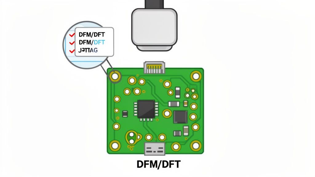
Actionable DFT: How Test Points Save Weeks of Debug
Design for Testability is about building observability and controllability into your hardware from the very beginning. Adding well-placed test points to your initial schematic is one of the highest-leverage activities in the NPI process. That small upfront investment pays for itself tenfold during board bring-up and production.
Your manufacturing test plan shouldn't be an afterthought; it should be a living document that starts alongside the system architecture. This forces critical conversations early. If the firmware team is planning a secure bootloader, how will the factory securely flash the initial image onto 10,000 units? If you don't define the programming protocol and design the fixture interface from day one, you are setting your CM up for failure.
Consider the power of a JTAG/boundary scan chain. By adding a header and connecting the test access port (TAP) signals on your major ICs, you gain a powerful debugging interface. When an EVT board is dead on arrival, you don't have to waste days probing with a multimeter. Instead, you can immediately check for open pins, shorted connections, and verify that every chip in the chain is correctly placed and powered. Our guide on Design for Manufacturing offers more detailed strategies if you want to dig deeper. This is how you shave weeks off your bring-up schedule.
Orchestrating Your Supply Chain and Manufacturing Readiness
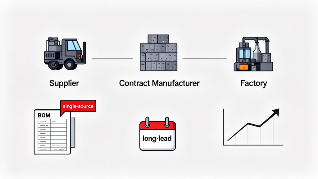
A brilliant product design is worthless if you can’t build it reliably and at scale. Your product’s fate is as dependent on your supply chain as it is on your engineering. A technically perfect design that relies on a single-source component or an incapable Contract Manufacturer (CM) is a program risk waiting to happen.
This is why a disciplined approach to vetting and managing your suppliers is a non-negotiable part of any serious new product introduction. It means looking past unit cost and asking hard questions about a partner's technical depth and process maturity. Can their engineers understand and act on your DFM feedback? Do they have a robust quality management system? These factors separate a true partner from a low-cost vendor. As you organize your internal processes, also consider the impact of 3D printing on production and supply chain for rapid tooling and bridge manufacturing.
Building a Resilient Ramp Plan
Your production ramp plan is the operational heartbeat of your launch. It is more than a timeline; it's a detailed blueprint that begins with a rigorous, line-by-line risk analysis of your Bill of Materials (BOM). The objective isn't to create a perfect plan—that's impossible. The goal is to build a plan that can withstand the shocks that will inevitably occur.
A solid BOM risk analysis must flag these critical items:
- Single-Source Components: Every part with only one supplier is a risk. You need a specific mitigation for each, whether that’s qualifying an alternate part, negotiating buffer stock, or redesigning it out completely.
- Long-Lead Items: Identify any component with a lead time that stretches past your normal production cycle. These parts need to be ordered far in advance to prevent line-down situations.
- End-of-Life (EOL) Status: Check the lifecycle status of every component. Designing in a part that’s about to go EOL can trigger a costly, last-minute redesign right when you should be scaling.
Operating Scenario: A Robotics Startup in the Trenches
A robotics startup is gearing up for the first production run of its new warehouse drone. Their DVT builds went well, and they’re barreling towards the PVT run with their chosen CM. Then, two issues erupt simultaneously.
First, the CM becomes unresponsive. Status reports on fixture readiness are vague, and questions about the secure firmware flashing process are brushed off. At the same time, the purchasing team sounds the alarm: there's a global shortage of the microcontroller at the core of their navigation system.
This is a classic NPI pressure cooker. The team's response will determine the launch's success.
The natural impulse is to focus on the component shortage—it feels like the most urgent fire. But the ambiguous communication from the CM is the far more dangerous, systemic threat. A weak partner will keep generating new problems, while a component shortage is a finite crisis you can manage.
The program manager immediately spins up two teams. One group works on the microcontroller crisis, escalating with the supplier and collaborating with engineering to start validating a drop-in replacement as a plan B.
The second, more senior team gets on a plane. They are dispatched to the CM’s factory for an emergency readiness review, armed with a detailed checklist. The directive is simple: don't leave until you’ve walked the line and seen every process with your own eyes.
A CM Readiness Review Template
A proper readiness review is not a conference call; it's a physical audit on the factory floor. Your checklist needs to be ruthlessly specific, leaving zero room for interpretation.
Tooling and Fixtures:
- Have all assembly jigs been qualified using production-intent parts, not 3D-printed stand-ins?
- Are the test fixtures for both ICT and functional test fully operational and calibrated?
- Have Golden Units (one known good, one known bad) been run through the line to prove the fixtures can actually catch failures?
Process and Documentation:
- Are the Standard Operating Procedures (SOPs) for assembly clear, visual, and posted at every single station?
- Is the secure firmware flashing station physically isolated with strict access controls? Who has the keys?
- Is a Failure Reporting, Analysis, and Corrective Action System (FRACAS) in place to capture, analyze, and fix every single failure that occurs on the line?
This is the kind of granular, in-the-weeds orchestration that defines manufacturing readiness. It’s how you stop being a customer and start being a partner, ensuring your product gets from a handful of prototypes to thousands of units rolling off the line without any nasty surprises.
Managing Risk and Ensuring Field Readiness
A successful new product introduction isn't about avoiding every problem. That's an impossible standard. Real success comes from anticipating the most critical failures and building robust systems to mitigate them before they can derail your program or damage your brand in the field.
This is where disciplined, proactive risk management becomes your most valuable asset. This isn't a risk register that gets filed away and forgotten. This is a living program risk map that turns potential failures into concrete engineering tasks with clear ownership.
Building Your Program Risk Map with FMEA
The bedrock of a solid risk map is the Failure Mode and Effects Analysis (FMEA). This is a bottom-up method that forces your team to systematically identify every conceivable way your product could fail—in design, during manufacturing, or in the field. It requires your team to think like pessimists, which is the mindset needed to build a truly reliable product.
For each potential failure, you analyze its effects and score three key factors:
- Severity (S): How catastrophic is the failure if it occurs? (1 = minor hiccup, 10 = safety hazard or total system failure)
- Occurrence (O): How likely is this failure mode to occur? (1 = extremely unlikely, 10 = almost certain)
- Detection (D): How likely are you to catch this before it reaches a customer? (1 = will definitely be caught, 10 = cannot be detected)
Multiplying these scores gives you a Risk Priority Number (RPN). This isn't an abstract metric; it's a data-driven command that tells you exactly where to focus your engineering resources. A high RPN screams, "Fix this now."
NPI Common Failure Modes and Mitigation Strategies
Throughout the NPI process, certain pitfalls appear time and time again. From misaligned requirements in the concept phase to last-minute component shortages during ramp-up, these issues can quickly escalate if not anticipated. Recognizing these common failure modes is the first step toward building a resilient plan.
The table below summarizes some of the most frequent challenges we see in complex electronics development, mapping them to their root causes and outlining proactive strategies to keep your program on track.
| Failure Mode | Phase of Impact | Root Cause | Mitigation Strategy |
|---|---|---|---|
| Requirement Creep | Concept, EVT | Poorly defined initial scope; lack of a formal change control process. | Implement a robust Product Requirements Document (PRD) with stakeholder sign-off. Establish a formal Change Control Board (CCB) process. |
| Component Lead-Time Crisis | Prototype, Ramp | Inaccurate forecasting; single-sourcing critical parts; late BOM finalization. | Engage with suppliers early. Identify long-lead-time components and secure buffer stock or pre-order. Qualify second sources for all critical parts. |
| Poor Testability | EVT, DVT | Design for Test (DFT) not prioritized; insufficient test point access. | Integrate DFT reviews into the schematic design phase. Mandate test point access for critical signals. Develop test firmware concurrently with hardware. |
| Manufacturing Yield Bust | DVT, Production | Design for Manufacturability (DFM) ignored; unrealistic tolerances. | Conduct DFM/DFA (Design for Assembly) reviews with the Contract Manufacturer (CM) before finalizing the layout. Run a pilot build to validate the process. |
| Firmware-Hardware Mismatch | EVT, DVT | Siloed development teams; poor communication on hardware revisions. | Maintain a hardware/firmware compatibility matrix. Use a centralized version control system for both hardware (e.g., schematics, layout) and firmware. |
| Regulatory Compliance Fail | V&V, Compliance | Late engagement with compliance labs; designing without standards in mind. | Identify target markets and their specific compliance needs (e.g., FCC, CE, UL) during the concept phase. Perform pre-compliance testing early and often. |
By proactively addressing these common issues, you shift from a reactive, fire-fighting mode to a more strategic and controlled NPI execution. This not only de-risks the launch but also saves significant time and budget in the long run.
From Analysis to Action: The Risk Burndown Plan
An FMEA is worthless without an aggressive risk burndown plan. Every high-RPN item needs a specific mitigation task assigned to a single owner. Vague ownership is the same as no ownership—make one person responsible.
The goal isn’t just to lower the RPN score. The real leverage is in driving the Detection (D) score down as close to 1 as possible. You might not be able to completely eliminate a rare failure mode, but you can almost always improve your ability to catch it. This is where your investment in Design for Testability (DFT) pays massive dividends. Can you add a simple test point? A self-test routine in the firmware? An automated check in your manufacturing test jig? If you want to dive deeper, we have a detailed guide on how to test a printed circuit board.
A risk burndown chart is the EKG of your program's health. If that line isn't trending down week over week, your program is getting riskier, not safer—no matter how "on schedule" it might look on a Gantt chart.
Designing for Field Readiness and Rapid Response
Your job isn't done when the product ships. Some of the most valuable data comes from real-world failures. But if you haven’t built in the right instrumentation, that precious data is lost forever.
This is why robust logging and telemetry must be designed into your firmware from day one. When a device fails in the field, you shouldn't have to ship it back and spend weeks in the lab trying to replicate the problem. You need the ability to remotely pull detailed logs that paint a clear picture of the system's state moments before failure.
The other linchpin of field readiness is a well-architected Over-the-Air (OTA) update mechanism. A secure and reliable OTA system is your ultimate safety net. It gives you the power to deploy critical bug fixes without the catastrophic expense and brand damage of a full product recall.
However, a poorly implemented OTA system can be more dangerous than the problem it’s meant to solve. You must consider the failure modes here, too:
- Rollback Mechanisms: What happens if an update fails halfway through or introduces a new, even worse bug? Your device must have a "golden" backup image it can automatically revert to. This is a non-negotiable requirement for reliable systems.
- Security: Your update pipeline is a massive target for attackers. It must be locked down with cryptographic signatures to ensure only authenticated, official firmware can ever be installed.
- Compatibility: How will your update handle different hardware revisions in the field? Your OTA logic must be able to identify the device's specific hardware and apply the correct firmware version.
Thinking through these second-order failures before you ship is the essence of building a resilient product and a brand that customers trust.
Your New Product Introduction Questions Answered
Even the most buttoned-up new product introduction process will have challenges. Program managers and engineering leads are constantly forced to make high-stakes tradeoffs under pressure. These are some of the most common—and critical—questions that arise when bringing complex electronics to market.
How Early Should We Engage A Contract Manufacturer?
Far earlier than most teams think. For any product with real complexity, initial conversations with a Contract Manufacturer (CM) should happen during the architectural design phase. Do not wait until your design is “done.”
Bringing a CM partner in this early is your best defense against future pain. They provide the critical Design for Manufacturability (DFM) feedback that is essential for your layout, component selection, and assembly strategy. That early input prevents costly redesigns later. At an absolute minimum, a CM must be selected and fully engaged before your first EVT build to ensure prototypes are built with production in mind from day one.
What Is The Biggest Mistake Companies Make In The DVT Phase?
The single most damaging mistake is the "soft" design freeze. Teams, eager to show progress, often rush into a Design Validation Test (DVT) build while allowing “minor” hardware tweaks or last-minute firmware changes to sneak in.
This completely undermines the purpose of DVT, which is to rigorously validate a fixed, final design against all of its requirements. A disciplined design freeze, enforced with a rigid Engineering Change Order (ECO) process, is non-negotiable for a meaningful DVT.
When you allow informal changes, you're chasing a moving target. It becomes impossible to know if a failure is from a fundamental design flaw or from an untested, last-minute tweak.
Can We Skip A Pilot Run If Our DVT Builds Had High Yield?
This is a common temptation and an extremely risky gamble. A high yield during DVT builds is fantastic news, but it proves something entirely different from a pilot run, or Production Validation Test (PVT).
- DVT proves the design is buildable under near-ideal conditions, often with senior engineers hand-holding the process in a low-volume lab.
- PVT proves the mass production process is stable and repeatable at scale. This is where you validate the final tooling, automated fixtures, operator training, and the entire supply chain under real volume pressure.
Skipping the pilot run frequently leads to disastrous yield crashes and quality escapes right as you’re ramping up production—precisely when market expectations are at their highest.
The landscape for launching a product has also grown more complex. It's not just about engineering readiness; it's about market awareness. The dynamics of product discovery have fundamentally shifted, with consumers now discovering brands through an average of 5.8 different sources. Search engines lead as a discovery channel for 32.8% of internet users, but social media's influence has surged by 11.7% in just two years. For companies launching complex electronics, this underscores the need for a coordinated strategy across multiple channels to ensure your new product introduction finds its audience. Explore more on how brand discovery is evolving.
Your product's success depends on rigorous engineering and a clear path from prototype to production. If you're facing challenges in your NPI process, Sheridan Technologies can provide the technical leadership and execution support to de-risk your program.