
Table of Contents
When developing a connected product, the choice of communication protocol is a foundational decision that impacts power consumption, bill of materials, and deployment risk. For Low-Power Wide-Area Networks (LPWAN), the LoRaWAN communication protocol is a frequent contender, but a massive gap exists between datasheet promises and a reliable, production-ready system. A misunderstanding of LoRaWAN’s core trade-offs can lead to failed field deployments, crippling battery life issues, and costly product redesigns.
This guide is for the CTOs, VPs of Engineering, and lead systems engineers accountable for delivering robust IoT devices. It’s for teams building industrial, agricultural, or logistics products where connectivity failure means operational failure. We will move past marketing claims and dig into the engineering decisions and operational realities of implementing LoRaWAN.
Here’s what this guide delivers:
- A breakdown of the LoRaWAN architecture and its implications for system design and debugging.
- Decision criteria for selecting the correct device class based on latency and power constraints.
- A practical framework for implementing production-grade LoRaWAN security.
Problem: Why LoRaWAN Architecture Decisions Derail Products
Misunderstanding the LoRaWAN architecture is a primary source of project risk. We’ve seen teams burn weeks debugging the wrong layer of the stack or making firmware choices that destroy battery life because they mistook a LoRaWAN gateway for a simple Wi-Fi access point. For any engineering team, knowing where one component’s responsibility ends and the next begins is critical for efficient design, verification, and field debugging.
A LoRaWAN network is a distributed system with four distinct components: End Devices, Gateways, a Network Server, and an Application Server. This deliberate separation of concerns is what enables its scalability and resilience, but it also creates boundaries that must be respected in your product’s architecture.
The Four Pillars of a LoRaWAN System
- End Devices: These are your sensors or actuators deployed in the field. They use the LoRa physical layer (PHY) to transmit small, encrypted data packets over long distances. Their core function is to collect and transmit data with maximum power efficiency.
- Gateways: A gateway is a simple RF-to-IP bridge. It listens for LoRa RF packets from any device in range, converts them to IP packets, and forwards them to the Network Server. A gateway is agnostic to the data payload; it has no keys and simply passes along what it hears.
- Network Server (LNS): This is the central controller of the network. The LNS is responsible for de-duplicating messages received by multiple gateways, managing device authentication and session keys, and controlling network-level behavior via MAC commands (like Adaptive Data Rate). It is the brain of the network infrastructure.
- Application Server (AS): This is where your data generates business value. The Application Server receives the encrypted payload from the LNS, decrypts it, and processes the application-specific data. It integrates with your cloud platform, dashboards, or other enterprise systems.
This architecture is precisely what allows LoRaWAN to deliver on its core promises of long range, low power, and massive device scalability.
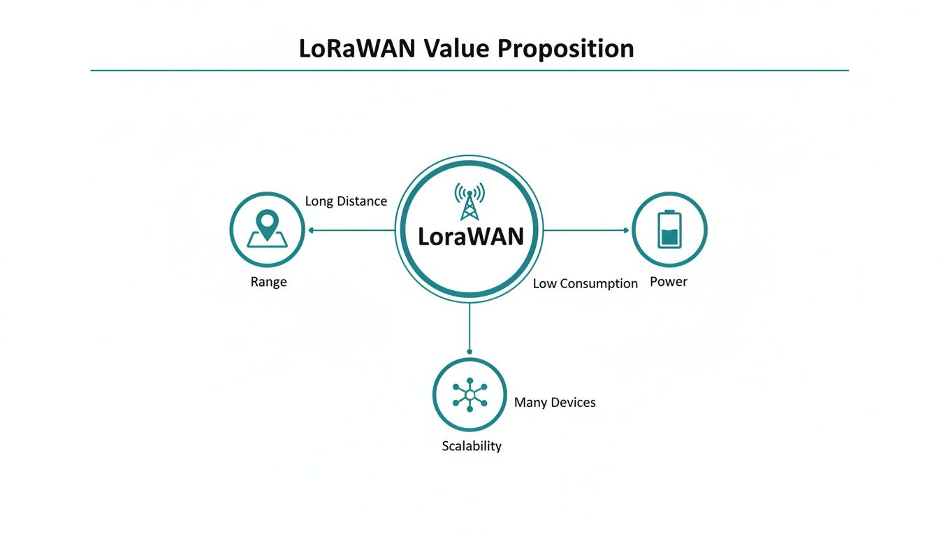
These three benefits are direct outcomes of this defined structure, making LoRaWAN a powerful choice for large-scale IoT deployments where traditional connectivity like WiFi for IoT is not feasible due to range or power constraints.
Data Flow From Sensor to Cloud
Let’s trace a single data packet to illustrate the process. An End Device wakes from a deep sleep, takes a sensor reading, and broadcasts an encrypted LoRa packet. Any Gateways within range receive this RF packet and forward it over an IP backhaul (like Ethernet or cellular) to the Network Server.
The LNS sees the incoming messages. If three gateways heard the same packet, the LNS de-duplicates them, keeping only one copy. It then verifies the message’s integrity and confirms the device’s identity. The server might then queue a command back to the device, like an instruction to adjust its transmission power via Adaptive Data Rate (ADR).
The LNS’s role is network management, not data interpretation. It routes the encrypted application payload to the correct Application Server but has no keys to read it. This is a critical security and architectural feature that separates network operations from application data ownership.
Finally, the LNS forwards the authenticated, still-encrypted payload to the designated Application Server. Only the Application Server holds the session key to decrypt the payload, revealing the sensor data (e.g., “temperature: 21.5°C”). This is where raw data becomes business value. For instance, in our work with IoT and fleet management, this is where raw GPS coordinates are processed into actionable route optimization data. The entire IoT system, from device to cloud, must be considered as part of a cohesive design, as outlined in a broader guide to IoT application development.
This ecosystem has achieved massive scale. As of late 2023, the LoRa Alliance reported that global deployments exceeded 125 million devices, a testament to the protocol’s maturity and suitability for large-scale industrial and utility applications. You can review the specifics in the LoRa Alliance’s full report on global deployments.
Decision: Selecting the Right Device Class
One of the first and most critical architectural decisions for a LoRaWAN product is selecting the device class. This choice dictates the fundamental trade-off between downlink latency (how quickly the device can receive a command) and battery life. Getting this wrong can result in batteries that die in months instead of years or a system that is unacceptably unresponsive for its use case.
The LoRaWAN specification defines three device classes—Class A, Class B, and Class C—each engineered for a different operational scenario. Understanding their mechanics is non-negotiable for firmware and hardware engineers.
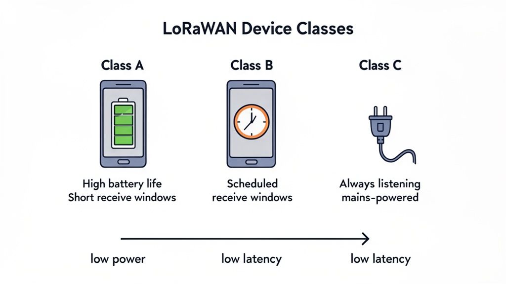
Class A: The Power Efficiency Champion
Class A is the default and the most power-efficient class. It is designed for devices that must operate for years on a single battery.
A Class A device spends nearly all its time in a deep sleep state. When it has data to send (an “uplink”), it wakes, transmits, and then opens two brief “receive windows” to listen for a response (a “downlink”) from the network. If no downlink is pending, the device immediately returns to sleep.
This asynchronous, device-initiated communication model has critical consequences:
- Extreme Battery Life: With the radio powered off >99% of the time, Class A is the only viable choice for achieving multi-year battery performance from a small power source.
- High Downlink Latency: The network can only send a command to the device during the two short windows following an uplink. This means downlink latency is unpredictable and can range from minutes to days, depending on the device’s reporting interval.
- Ideal for “Set and Forget” Sensors: Class A is perfect for applications like smart water meters, agricultural soil sensors, or simple asset trackers that report on a predictable, infrequent schedule.
Class B: The Balanced Latency Performer
Class B offers a compromise, providing predictable downlink latency without the severe power penalty of Class C.
In addition to the standard Class A receive windows, Class B devices periodically open extra, scheduled receive windows called “ping slots.” The timing of these slots is synchronized across the network via a time-synchronized beacon broadcast by gateways. This allows the Network Server to know exactly when a device will be listening.
This approach provides a deterministic window to reach the device, making it suitable for applications that require more frequent control, such as remote valve actuators, irrigation controllers, or building automation systems that need periodic adjustments.
Class C: The Low-Latency Responder
Class C provides the lowest possible downlink latency at the cost of significantly higher power consumption. Class C devices keep their radio receiver open almost continuously.
A Class C device is essentially always listening for a downlink, except for the brief moments it is transmitting. This enables near real-time communication but consumes 50-100x more power than a Class A device, making it completely unsuitable for battery-powered applications.
Due to its high power draw, Class C is only feasible for mains-powered devices. It is the correct choice for systems where immediate action is required, such as industrial process controllers, smart street lighting, or emergency shut-off systems. You can send a command at any moment and expect the device to act on it almost instantly.
LoRaWAN Device Class Decision Framework
Choosing the right device class is a primary architectural trade-off. This table summarizes the decision criteria based on your product’s operational requirements.
| Attribute | Class A (Lowest Power) | Class B (Balanced) | Class C (Lowest Latency) |
|---|---|---|---|
| Primary Goal | Maximize battery life | Balance latency and battery life | Minimize downlink latency |
| Power Profile | Ultra-low (µA in sleep) | Low (Periodic mA spikes for ping slots) | High (Continuous mA draw) |
| Downlink Latency | Highest (minutes to days) | Predictable (seconds) | Lowest (< 1 second) |
| Communication Style | Asynchronous (device-initiated) | Synchronized (time-based receive slots) | Always-on (continuous listening) |
| Typical Power Source | Small battery | Battery or mains-powered | Mains-powered |
| Ideal Application | “Fire and forget” sensors, metering, basic tracking | Periodic control, remote actuators | Real-time control, lighting, industrial automation |
Recommendation: If your device reports data infrequently and must run for years on a coin cell, Class A is your only choice. If you need to send scheduled commands without sacrificing battery life completely, Class B is a strong candidate. If your device is mains-powered and requires immediate responsiveness, Class C is the clear solution.
Recommendation: Implement a Multi-Layered Security Strategy
For industrial, medical, or critical infrastructure products, security is not a feature; it is the foundation of operational integrity and customer trust. A security breach can lead to data theft, service disruption, or physical safety hazards. The LoRaWAN communication protocol incorporates security by design, but achieving production-grade security requires a deliberate, multi-layered implementation.
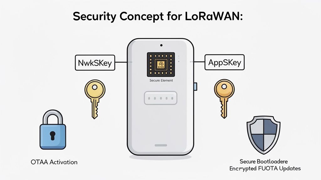
Core Security Primitives: NwkSKey and AppSKey
LoRaWAN’s security model is built on two distinct 128-bit AES session keys, creating a crucial separation of concerns.
- Network Session Key (NwkSKey): Shared between the end device and the Network Server, this key protects the integrity of the network itself. It is used to authenticate messages (Message Integrity Code) and ensure that network-level commands are legitimate and have not been tampered with.
- Application Session Key (AppSKey): Shared exclusively between the end device and the Application Server, this key provides true end-to-end encryption for the data payload. The Network Server cannot read the application data; it only sees an encrypted blob.
This dual-key architecture is a powerful feature. It allows a network operator to manage network traffic and health without having access to the sensitive application data. For any product handling confidential information, this is a non-negotiable security control.
The OTAA vs. ABP Decision: One Right Answer for Production
Before a device can communicate, it must join the network and derive its session keys. LoRaWAN provides two methods, but for any professional product, only one is acceptable.
- Activation by Personalization (ABP): The session keys (NwkSKey, AppSKey) and device address are hardcoded onto the device during manufacturing. While simple for prototyping, ABP is a significant security liability. The keys are static; if a device is physically compromised, its keys are permanently exposed.
- Over-the-Air Activation (OTAA): This is the mandatory method for production. The device is provisioned with a globally unique DevEUI and a secret root key (AppKey). During a “join procedure,” the device and network authenticate each other and dynamically generate unique session keys for that communication session.
Sheridan’s Point of View: We mandate OTAA for all production systems. ABP creates a static attack surface that is unacceptable for high-reliability products. The use of session-specific keys in OTAA ensures that compromising a single device’s session does not compromise its past or future communications. This aligns with our core principle of building in security from the start.
Protecting Against Replay Attacks and Securing Keys
LoRaWAN includes a native defense against replay attacks. Each uplink and downlink message contains a frame counter that must increment with every transmission. The Network Server tracks the last counter value from each device and will reject any message with a repeated or older value. This prevents an attacker from capturing a valid transmission and replaying it later to trigger a false action.
The entire security model hinges on protecting the root keys, especially the AppKey used in OTAA. These keys must be stored in a hardware secure element (SE) or a trusted execution environment on the device’s microcontroller. Storing keys in standard flash memory makes them vulnerable to physical extraction and should be considered a critical design flaw.
Finally, a complete security strategy must cover the entire device lifecycle. A secure bootloader ensures that only authenticated firmware can run on the device, while cryptographically signed firmware-over-the-air (FUOTA) updates are essential for maintaining device integrity in the field. For a deeper dive, review our guide on IoT security best practices and consider incorporating formal vulnerability assessment and penetration testing into your verification plan.
Risks & Failure Modes: Regional Parameters and Link Behavior
Deploying a LoRaWAN product globally is a regulatory and engineering challenge. Unlike globally harmonized bands for Wi-Fi or Bluetooth, the LoRaWAN communication protocol operates on regional ISM (Industrial, Scientific, and Medical) bands. A device designed for North America (US915) is illegal to operate and will not function in Europe (EU868) or most of Asia (AS923).
This has direct consequences for hardware selection and firmware development. Your team must manage different frequency plans, channel masks, and the most critical operational constraint: duty cycle limitations.
The Critical Constraint of Duty Cycle
A duty cycle is a legal limit on how much time a device can spend transmitting in an unlicensed band. It is designed to ensure fair use of the shared spectrum. In many European regions, the duty cycle is 1% for common sub-bands.
If a device’s transmission takes 100 milliseconds, it must then remain silent for at least 9.9 seconds. This is not a suggestion; it is a regulatory requirement enforced by the LoRaWAN stack. Ignoring this constraint during the design phase can render a product non-viable.
Sheridan’s Point of View: We’ve seen product roadmaps get completely derailed by teams treating duty cycle as an afterthought. It must be a primary design constraint. If your use case requires a 10-second reporting interval in a region with a 1% duty cycle limit and your packet takes >100ms to transmit, your product is fundamentally non-compliant and requires a major architectural redesign.
This forces a disciplined approach to data transmission, making mechanisms like Adaptive Data Rate essential for compliance and performance.
Optimizing Performance with Adaptive Data Rate (ADR)
Adaptive Data Rate (ADR) is a network-managed mechanism to optimize device battery life and overall network capacity. It is a closed-loop system where the Network Server analyzes a device’s signal quality and instructs it to adjust its transmission parameters.
The ADR logic is straightforward:
- Monitor Signal Quality: The LNS tracks the Signal-to-Noise Ratio (SNR) of recent uplinks from a device.
- Make a Decision: If the signal is strong, the server concludes the device can transmit faster (use a lower spreading factor) or reduce its transmit power.
- Send MAC Command: The server sends this instruction (
LinkADRReq) to the device in the next available downlink window. - Device Acknowledges: The device applies the new settings and acknowledges the change.
A well-implemented ADR strategy dramatically improves battery life and reduces airtime, freeing up network capacity. With the LoRaWAN market projected to grow from USD 10.88 billion in 2025 to USD 144.71 billion by 2034, according to a market analysis on Fortune Business Insights, this network efficiency is critical for scalability.
However, ADR has a significant failure mode: it assumes the device is stationary. For mobile assets, like a tracker on a vehicle, RF conditions change constantly. ADR may instruct a device to reduce power just before it moves behind a building, causing message loss. For mobile applications, it is often safer to disable ADR and use a fixed, robust data rate.
Confirmed vs. Unconfirmed Messages: A Common Pitfall
Firmware teams must choose between unconfirmed and confirmed messages.
- Unconfirmed Uplinks: The device transmits its data and immediately goes to sleep. This is the most efficient method, using the least power and airtime.
- Confirmed Uplinks: The device transmits and then listens for an acknowledgment (ACK) from the network. If no ACK is received, it re-transmits.
While confirmed messages seem more reliable, they come at a high cost to the network. Every ACK is a downlink, and gateway downlink capacity is a severely limited resource. Overusing confirmed messages is a classic anti-pattern that creates network congestion, exhausts gateway duty cycle limits, and can cause cascading failures. The best practice is to use unconfirmed messages for routine data and build application-layer logic to detect and handle data gaps. Confirmed messages should be reserved for rare, critical events like acknowledging a firmware update command.
Next Steps: A Verification Strategy for Production-Ready LoRaWAN Devices
Moving from a lab prototype to a scalable, manufacturable product requires a rigorous verification strategy. A casual “it seems to work” approach is a direct path to field failures and manufacturing stalls. A structured verification plan de-risks the program and ensures that what you designed is what gets built.
RF Performance and Antenna Validation
Your device’s ability to communicate reliably starts and ends with its RF performance. You cannot trust a module datasheet alone.
- Transmit Power and Sensitivity: Using a spectrum analyzer and RF signal generator, you must conductively verify that the transmit power meets your link budget and receive sensitivity matches the specification. This validates the radio’s health before the antenna is even connected.
- Antenna Matching and Performance: An impedance mismatch between the antenna and the radio’s 50-ohm output will reflect power, kill range, and drain the battery. Use a Vector Network Analyzer (VNA) to confirm a good match (low S11). Follow this with Over-the-Air (OTA) testing in an anechoic chamber to characterize the antenna’s true radiation pattern and efficiency.
Firmware and Hardware-in-the-Loop (HIL) Testing
Once the RF front-end is validated, you must rigorously test the firmware’s LoRaWAN stack implementation.
- Unit Tests: Isolate and test individual functions for packet formatting, encryption, and MAC command handling. These tests provide an early warning for low-level bugs.
- Hardware-in-the-Loop (HIL) Simulation: Connect your device to a test rig that emulates a LoRaWAN gateway and network server. This allows you to script complex and negative scenarios that are impossible to reproduce reliably over the air. You can torture-test join-request backoffs, ADR behavior under fluctuating signal conditions, and recovery from network failures.
HIL testing is your single best defense against intermittent field failures. You can simulate a month of chaotic network conditions in a day, intentionally injecting faults to prove your firmware’s resilience.
Design for Testability on the Production Line
A device you can’t test efficiently is a device you can’t build at scale. Design for Testability (DFT) involves building test hooks into your hardware and software from the beginning.
Create a dedicated manufacturing test firmware. This stripped-down build allows a production line fixture to rapidly validate each unit in seconds. The fixture should be able to:
- Command a test transmission to confirm the radio works.
- Securely provision the device with its unique identifiers and security keys (DevEUI, AppKey).
- Run a quick functional check on other critical hardware like sensors.
This turns a multi-minute manual process into a sub-30-second automated one, increasing throughput and ensuring every device is fully functional and correctly provisioned before it ships. The reliability enabled by such practices is why LoRaWAN has become a leading choice for massive deployments, as detailed in reports about how spec upgrades are boosting smart facility deployments.
At Sheridan Technologies, we specialize in navigating these technical trade-offs to build reliable, production-ready connected products. If your team is facing challenges with LoRaWAN implementation or needs a partner to accelerate your prototype-to-production timeline, we can help.
Schedule an architecture consult with our engineering team to review your LoRaWAN strategy.