
Table of Contents
At its heart, embedded systems development is the disciplined process of designing, building, and delivering a specialized electronic product that merges hardware with custom software. For technical leaders, program managers, and lead engineers, this isn’t just about writing code or soldering a board; it’s an end-to-end journey from a system requirements document to a shippable, reliable product. The stakes are high: a flawed process leads to crippling delays, budget overruns, and field failures that can destroy a product’s reputation.
This guide provides a unified framework for teams building high-reliability systems for demanding fields like medical, industrial, or aerospace. It is not intended for hobbyist projects where a “just make it work” approach is sufficient. Instead, it outlines a battle-tested process designed to de-risk complex programs and ensure a smooth handoff to manufacturing. The goal is to equip decision-makers with a practical roadmap for navigating the entire development lifecycle, from initial architecture to final production.
This article will show you how to:
- Structure the development process for maximum efficiency and risk reduction.
- Make critical architecture decisions that align with technical and business goals.
- Plan for verification, validation, and manufacturability from day one.
The Complete Embedded Systems Development Lifecycle
Successful embedded systems development hinges on moving past the siloed approach where hardware and software teams toss deliverables over the wall. Instead, it requires an integrated, end-to-end process that treats the product as a single, cohesive system. A poor architectural choice made in month one can have a massive ripple effect, blowing up costs and wrecking the schedule in month nine.
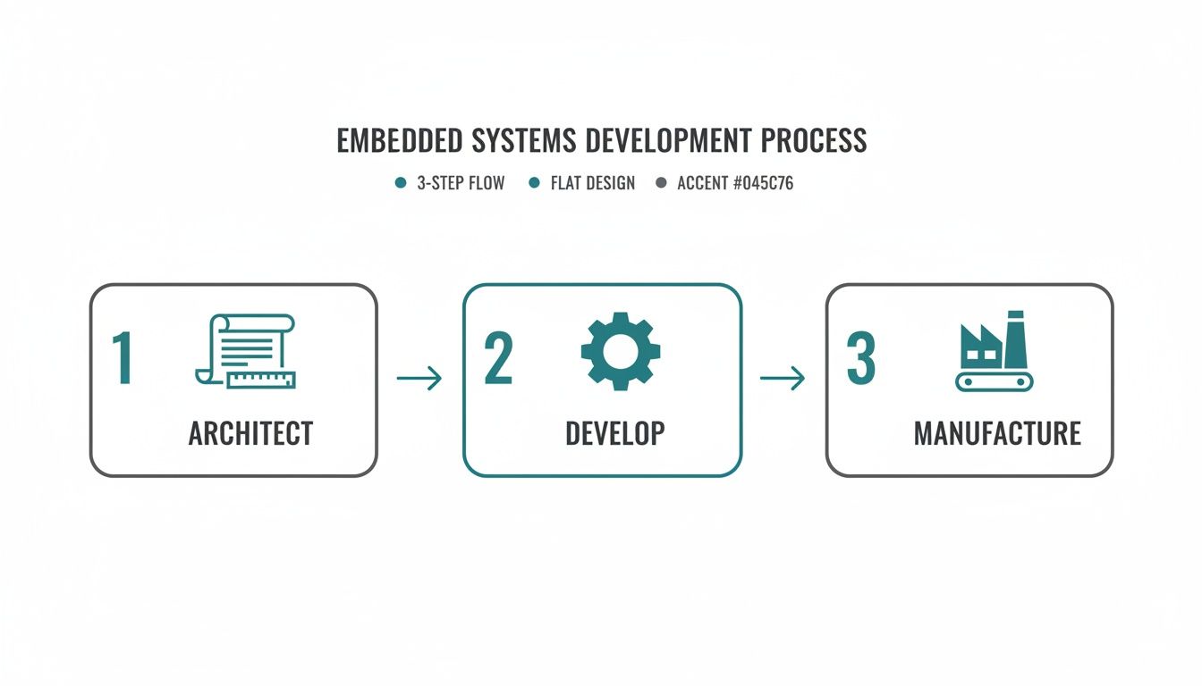
Getting this integration right is a core principle at Sheridan Technologies. We champion a holistic, prototype-to-production mindset because we’ve repeatedly seen the consequences of a disjointed process. The entire journey can be broken down into three major phases: architect, develop, and manufacture. Each stage builds on the last, and manufacturing constraints must inform the very first architectural choices.
This interconnected flow is critical because the demand for this discipline is intensifying. The global embedded systems market, valued at USD 117.05 billion in 2025, is projected to surge to USD 213.62 billion by 2035, reflecting a steady CAGR of 6.20%. This growth is heavily concentrated in high-stakes sectors like automotive, healthcare, and industrial automation where a rigorous development process isn’t just best practice—it’s mandatory for survival. Read the full research about embedded market growth.
Architecting Your System and Selecting Technology
The architecture phase is where you make high-stakes decisions that define your product’s cost, performance, and path to market before a single component is ordered. A flawed architecture, built on vague requirements or incorrect assumptions, is one of the fastest ways to lock in expensive rework and crippling delays. This is the blueprint for your entire project, and it demands realism from day one.
This is the process of translating the “what” of your product requirements into the “how” of a concrete technical specification. It forces clarity on core functionality, performance targets, and operational constraints. At Sheridan, we embed manufacturing realism into these early design choices as a core philosophy for heading off risk before it can take root.
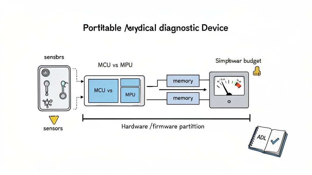
Realistic Scenario: A Portable Medical Diagnostic Device
Let’s ground this with a concrete operating scenario. A team is developing a portable medical diagnostic device under significant time-to-market pressure. The core constraints are unforgiving:
- Product Stage: Moving from a proof-of-concept to the first EVT (Engineering Validation Test) build.
- Timeline: A 6-month window to a demonstrable, verifiable prototype for a Series A funding round.
- Team: A small, 5-person team (2 hardware, 3 firmware) with limited program management overhead.
- Stakes: The device requires real-time data processing for diagnostic accuracy, must run for 8+ hours on a battery, and must be designed for eventual FDA 510(k) submission. Patient safety is a primary concern.
These constraints immediately force critical architectural tradeoffs. The need for both hard real-time processing and low-power operation creates a fundamental tension that directly drives the choice of processor and operating system. North America leads in such high-stakes development, capturing around 39% of global embedded systems revenue in 2025. The U.S. market alone hit USD 36.53 billion that year, fueled by relentless demand in healthcare and aerospace where these innovations are most critical. You can dig deeper into these market dynamics and trends.
The Critical MCU vs. MPU Decision
One of the first and most significant architectural decisions is choosing between a Microcontroller (MCU) and a Microprocessor (MPU). This choice fundamentally shapes the project’s cost, complexity, and capabilities.
At Sheridan, we see teams get this wrong frequently. They either over-engineer with a costly MPU they don’t need or under-engineer with an MCU that chokes when real-world processing loads hit. The choice must be rigorously justified by system requirements, not by what the team used on the last project.
For our medical device scenario, an MCU with strong real-time capabilities (like an ARM Cortex-M7) might be sufficient if the diagnostic algorithm is relatively simple. However, if the device requires a graphical user interface (GUI) and complex data analysis, an MPU running a high-level OS like Linux may be necessary, despite the increased power consumption and design complexity. The table below frames this decision.
MCU vs. MPU Selection Criteria
| Criterion | Microcontroller (MCU) | Microprocessor (MPU) | Sheridan’s Perspective |
|---|---|---|---|
| Integration | High (CPU, RAM, Flash, Peripherals on one chip) | Low (CPU only; requires external RAM, Flash, etc.) | MCU simplifies board design and reduces BOM cost. MPU offers flexibility but increases complexity and layout risk. |
| Operating System | Bare-metal or RTOS (Real-Time Operating System) | General-purpose OS (e.g., Linux, Android) | For hard real-time needs, an RTOS on an MCU is often superior. For complex applications needing networking and GUIs, an MPU with Linux is standard. |
| Power Consumption | Very low; optimized for sleep and low-power modes | Higher; optimized for performance over efficiency | The power budget is often a non-negotiable constraint driven by battery life requirements. This is a critical decision. |
| Cost at Scale | Lower per-unit cost | Higher per-unit and system cost (due to external components) | This is a classic DFM (Design for Manufacturability) consideration. Early architectural decisions have massive leverage on final unit cost. |
This decision, and its rationale, should be captured in an Architecture Decision Log (ADL). This document records what was decided and why, detailing the options considered and tradeoffs evaluated. An ADL is invaluable for keeping the team aligned and preventing foundational decisions from being argued over repeatedly.
Executing Hardware Prototyping and Board Bring-Up
Moving from a validated architecture to a physical prototype is where theory collides with the realities of electrons, silicon, and manufacturing tolerances. This stage, formally known as the Engineering Validation Test (EVT), is about building a small batch of boards to prove that the core design is sound before committing to more expensive production runs.
The journey starts with schematic capture and PCB layout, which is a disciplined craft that directly dictates performance and reliability. A perfect schematic can be completely undermined by a poor layout, creating a host of maddening signal integrity (SI) and power integrity (PI) problems.
From Layout to First Power-On
Great PCB layout hinges on a few non-negotiable requirements for a stable system. Cutting corners here is a classic recipe for costly board re-spins and schedule blowouts.
- Signal Integrity (SI): Ensuring signals are clean and undistorted requires managing trace impedance, length-matching high-speed pairs (e.g., USB, Ethernet), and preventing crosstalk.
- Power Integrity (PI): A stable power delivery network (PDN) is mandatory. This involves strategic placement of decoupling capacitors, low-impedance power planes, and ensuring rails can handle transient current demands without significant voltage droop.
- Design for Manufacturability (DFM): Thinking about the factory from day one is critical. This means choosing components your contract manufacturer (CM) can source and place, leaving adequate spacing, and designing panelization schemes that reduce cost.
At Sheridan, we treat the layout phase as a critical risk-reduction activity. A formal layout review is a mandatory gate before any design is sent for fabrication—it’s the last chance to catch subtle but fatal flaws before they’re etched in copper.
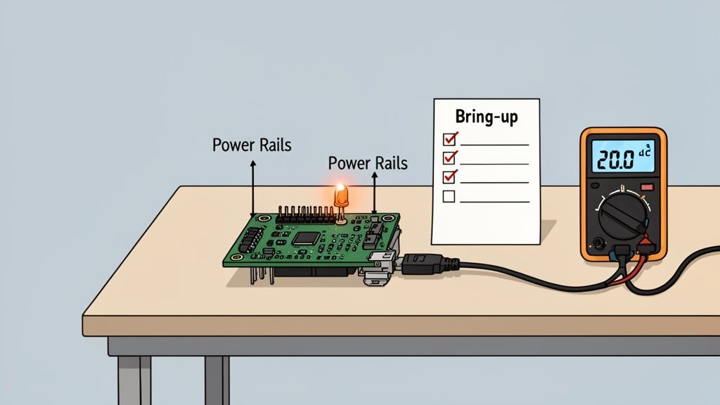
A Systematic Approach to Board Bring-Up
The moment of truth arrives when the first PCBs land on your bench. Powering on an untested board for the first time is a high-stakes moment. A chaotic “just plug it in” approach can easily fry components. A disciplined board bring-up plan turns this into a controlled, predictable process.
The point of bring-up isn’t to see if the whole system magically works. It’s to prove, subsystem by subsystem, that the hardware matches the design. The blinking LED is the classic first victory, but it’s the systematic validation of power rails, clocks, and resets that truly de-risks firmware development.
A solid bring-up plan almost always follows these stages:
- Visual Inspection: Before power is applied, inspect the board under a microscope for manufacturing defects like solder bridges or missing components.
- “Smoke Test”: Check for shorts between power rails and ground with a multimeter. Apply power for the first time using a current-limited power supply as a safety net.
- Power Rail Verification: Methodically measure all key power rails (e.g., 3.3V, 1.8V, 1.2V) to ensure they are stable and within tolerance.
- Clock Generation Validation: Use an oscilloscope to probe critical clock signals. Are they present, stable, and at the correct frequency? Without a clean clock, the processor is inert.
- Establish Debug Connection: Connect a debug probe (e.g., JTAG, SWD) and establish communication with the processor. This is the first confirmation that the chip is alive. For more on this, check our guide on debugging with JTAG.
- Basic Firmware Test: Load a minimal “blinky” program to flash an LED. This simple success proves the entire toolchain, compiling, flashing, and execution, is working and that the processor can fetch instructions from memory.
Developing and Integrating Reliable Firmware
If hardware is the skeleton, firmware is the central nervous system. It’s the specialized software living on the silicon that gives hardware its intelligence. This isn’t just about writing code that compiles; it’s about building a robust, testable, and maintainable software foundation that can survive in the real world for years.
One of the first big decisions is choosing the right software abstraction: bare-metal programming or a Real-Time Operating System (RTOS). This choice impacts complexity, real-time performance, and development velocity.
Choosing Between Bare-Metal and an RTOS
Bare-metal programming means your code runs directly on the processor with no OS. This gives absolute control and zero overhead, which is ideal for simple, single-purpose devices where every clock cycle and byte of RAM counts.
A Real-Time Operating System (RTOS) becomes essential when your system must juggle multiple, time-sensitive tasks concurrently. An RTOS acts as a lightweight scheduler, managing tasks (threads) to ensure everything runs on time.
For a connected medical device, an RTOS is almost certainly required. It might need to read vital signs from a sensor, update a display, maintain a wireless link, and respond to user input—all at the same time. An RTOS provides the structure (schedulers, mutexes, semaphores) to manage this complexity reliably, ensuring a critical sensor reading isn’t delayed by a screen refresh.
While an RTOS adds some complexity and memory overhead, for complex systems it’s often the only way to build a scalable and predictable product.
Core Patterns for Firmware Reliability
Whether using an RTOS or bare-metal, building trustworthy firmware comes down to battle-tested engineering patterns. These are the bedrock of a product that won’t require a 3 AM support call.
- Robust Peripheral Drivers: Each driver should be a self-contained module that exclusively manages one piece of hardware (e.g., sensor, flash chip) and is packed with error handling for hardware faults, timeouts, and corrupted data.
- Systematic Fault Tolerance: Assume things will go wrong. Implement watchdog timers to automatically reset a frozen system and brown-out detection to handle power sags without corrupting memory.
- Flexible Logging and Telemetry: A solid logging system that captures critical errors and system state is your lifeline for remote debugging. Make it configurable to adjust verbosity in the field.
- Testability Hooks: Build the firmware to be tested from day one. This involves creating special commands or interfaces (manufacturing firmware hooks) that allow factory test jigs to exercise hardware, calibrate sensors, and program unique identifiers during production.
Designing for Secure Over-the-Air Updates
For any connected device, the ability to push firmware updates remotely—Over-the-Air (OTA) updates—is a commercial necessity. A botched OTA mechanism, however, can turn thousands of devices into expensive bricks. Our complete guide on embedded firmware development services dives deeper into these challenges.
A resilient OTA process depends on several key components:
- Secure Bootloader: A small, protected piece of code that runs first to verify the digital signature of new firmware, preventing malicious or corrupted updates.
- Atomic Updates with Rollback: The update must be “atomic”—it either completes 100% successfully, or the device automatically reverts to the last known-good version. This is typically done using two separate memory banks.
- Compatibility Checks: The device must verify that new firmware is compatible with its specific hardware revision before starting the download, preventing incorrect updates.
By weaving these patterns into your development, you elevate your work from just writing code to engineering a truly resilient firmware foundation that is dependable, secure, and ready for a long life in the field.
Navigating Verification, Validation, and Compliance
A working prototype is not a market-ready product. The journey from a functional engineering build to a reliable, safe, and compliant product is a rigorous, systematic process of trying to break what you’ve built.
This phase is about answering two questions. First, Verification asks, “Did we build the system right?” It checks if the product meets the technical specifications defined during architecture.
Second, Validation asks, “Did we build the right system?” This confirms the product solves the customer’s problem in their real-world environment. For a deeper look at these concepts, read our guide on design validation and verification.
The Key Gates: DVT and PVT
This disciplined testing is structured around gates, with the two most important being the Design Validation Test (DVT) and the Production Validation Test (PVT). Skipping or rushing these stages leads directly to field failures and recalls.
At Sheridan, we see DVT and PVT as critical risk-reduction loops where you methodically hunt down design flaws before they become large-scale manufacturing problems. A bug caught during DVT costs dollars to fix; the same bug found after PVT can cost hundreds of thousands.
Design Validation Test (DVT): Your “design-intent” hardware is put through every conceivable test. A batch of 50 to 200 units is built to verify every functional requirement, stress the system to failure, and run initial compliance pre-scans (e.g., EMI/EMC).
Production Validation Test (PVT): This is the final dress rehearsal. Using the exact tooling, suppliers, and processes for mass production, you build a small run on the actual line. The goal is to prove you can build the product reliably at the required quality and speed.
Building a Comprehensive Test Plan
A successful V&V effort lives and dies by its test plan. This document is managed using a traceability matrix, a tool that creates an undeniable link between every product requirement, its corresponding design spec, the test case that verifies it, and the pass/fail results.
For firmware in industrial applications, understanding the logic behind control systems is non-negotiable. Reviewing real-world PLC example programs can provide valuable insights into structuring robust and testable control sequences, which directly informs your validation strategy.
The table below breaks down the purpose and key activities for each major development gate.
Embedded Development Gates: EVT, DVT, and PVT
| Phase | Primary Goal | Key Activities | Exit Criteria |
|---|---|---|---|
| EVT | Prove the core design is functional and meets basic requirements. | Bring-up, basic functional testing, power characterization. | Board powers on, core peripherals work, firmware can be loaded. |
| DVT | Verify the design is robust, reliable, and meets all specifications. | Full functional testing, environmental testing (temp/humidity), regulatory pre-compliance, stress and life testing. | All test cases passed, design is frozen, yields are acceptable. |
| PVT | Validate the manufacturing process and prove production readiness. | First run on the final assembly line, process capability studies (Cpk), final regulatory certification. | Production line is qualified, quality metrics are met, product is ready for mass production. |
By methodically pushing your product through these verification and validation stages, you are systematically de-risking your program. You’re not just hoping you have a great product; you’re proving it.
Designing for Manufacturing and Production Testing
An amazing design that can’t be built at scale is a commercial failure. Bridging the gap between a prototype and a profitable, high-volume product requires Design for Manufacturability (DFM) and Design for Testability (DFT) from day one.
This “prototype-to-production” mindset means you’re thinking about factory processes, component availability, and how you’ll test thousands of units a day while you’re still picking your microcontroller. A product that’s easy to build and quick to test is more profitable and more reliable.
Early DFM and DFT Strategies
Getting DFM and DFT right is a parallel track that runs alongside the entire design process.
Here are the strategies to implement from day one:
- Pick Components for Supply Chain Realities: Investigate a component’s lifecycle. Is it available from multiple distributors? What are the lead times? Choosing a sole-sourced part or one nearing end-of-life is a huge gamble that can halt your production line.
- Design Your PCB for Robots: Talk to your contract manufacturer (CM) early. Understand their equipment—standard panel sizes, component spacing requirements, and preferred fiducial markers. A board that is easy for their machines to handle translates to higher yields and lower costs.
- Create a Rock-Solid Test Point Strategy: Every critical voltage rail, clock, and data bus needs a dedicated test point. These are essential for automated In-Circuit Testing (ICT) on the factory floor.
Developing the Manufacturing Test Plan
Your manufacturing test plan is the playbook that guarantees every unit meets quality standards. It’s a detailed document defining every step from initial programming to final functional validation.
A solid plan must include:
- Specialized Factory Firmware: A purpose-built image designed to run a battery of tests, program unique IDs (serial numbers, MAC addresses), and burn in calibration data.
- A Scalable Test Fixture Strategy: For volume production, a “bed-of-nails” test fixture is non-negotiable. This custom hardware uses spring-loaded pogo pins to make simultaneous contact with all test points, enabling rapid, automated testing.
- Secure Flashing and Full Traceability: The plan must lock down how firmware is loaded to protect your IP. It also needs a system for logging the test results of every single unit, linked to a unique serial number for complete traceability.
A well-designed test fixture is more than a convenience; it’s a critical piece of production infrastructure. It’s the difference between testing 10 units an hour versus 100, and it’s your primary defense against shipping defective products.
By weaving DFM and DFT principles into your project from the start, you turn manufacturing from a risky variable into a predictable, controlled process. This directly slashes yield problems, accelerates time-to-market, and lowers the product’s true lifetime cost.
Common Questions About Embedded Systems Development
Even with the best-laid plans, building an embedded system is filled with tricky decisions. Over years of guiding products from concept to factory, we’ve found that technical leaders grapple with the same set of crucial questions. Here are practical answers to some of the most frequent ones.
What Is the Biggest Mistake Teams Make in Embedded Development?
By far, the most common and expensive mistake is treating manufacturing as a future problem. Teams that push Design for Manufacturability (DFM) and Design for Testability (DFT) to the final stages inevitably face a painful reality check, leading to significant rework, production delays, and soaring unit costs.
The most successful projects operate with a prototype-to-production mindset from day one. Every architectural choice, from component selection to PCB layout, is weighed against its impact on the factory floor. It’s the single most effective way to remove risk from a program.
When Should I Use an RTOS over Bare-Metal?
The choice comes down to system complexity and timing constraints.
Choose an RTOS when your system has to juggle multiple, time-sensitive tasks at once, like a medical device simultaneously processing sensor data, updating a display, and managing a network connection. An RTOS provides the scheduling and resource management needed to make it all work reliably.
Stick with bare-metal for simpler, single-purpose applications where tasks run sequentially and timing isn’t down to the microsecond. For a basic smart thermostat, an RTOS is often unnecessary overhead.
How Can I De-Risk My Hardware Bring-Up Process?
You de-risk board bring-up by creating a detailed, step-by-step bring-up plan before the first PCBs arrive. This plan should be a systematic checklist for validating each subsystem one at a time—power, clocks, reset, then the processor.
It starts with the initial power-up sequence, defining expected voltages and clock signals at specific test points. It then lays out a clear strategy for establishing a debug connection, like JTAG or SWD. This methodical approach helps pinpoint problems like shorts, incorrect footprints, or bootloader issues before they derail the schedule.
What Is the Purpose of an Architecture Decision Log?
An Architecture Decision Log (ADL) is a living document that captures the “why” behind your most important design choices. It records the major decisions, the reasons for them, and the other options considered and rejected. For example, an ADL would detail why your team chose a specific microcontroller, citing criteria like power consumption, available peripherals, and cost at scale.
This log provides critical context for new engineers and prevents “decision churn”—the wasteful cycle of re-litigating foundational choices. An ADL ensures the crucial thinking behind your system’s architecture isn’t lost as the project and team evolve.
Navigating the complexities of embedded systems development requires a partner with end-to-end expertise. Sheridan Technologies provides integrated hardware, firmware, and manufacturing readiness services to de-risk your program and accelerate your time-to-market. Schedule an architecture consult with our expert team to ensure your next project is built on a solid foundation.